[3.6.0-beta.4] Issues with Frequent M572 due to Adaptive PA
-
The pressure advance value is well tuned in my case but it happens to be optimal for the speed+acceleration it was measured with.
In general, higher PA values are needed at lower speeds and higher accelerations.
Adaptive PA is a feature that allows to change the PA value depending on the current speed and acceleration values by issueing M572 commands at every speed/accel change.
I tested the effect Adaptive PA using following small model (nothing special, but it shows the difference):
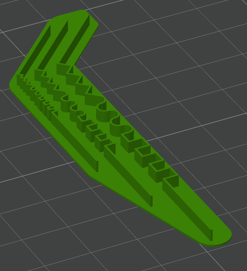
Source:
Extruder Limit TestUsing a "static" PA and a healthy jerk value of 7 for outer walls, the corners were quite rounded (left), because of the lower-than-measured-at speed for PA. In other words, in these regions with frequent changing directions the speed is slow and the PA value should be higher.
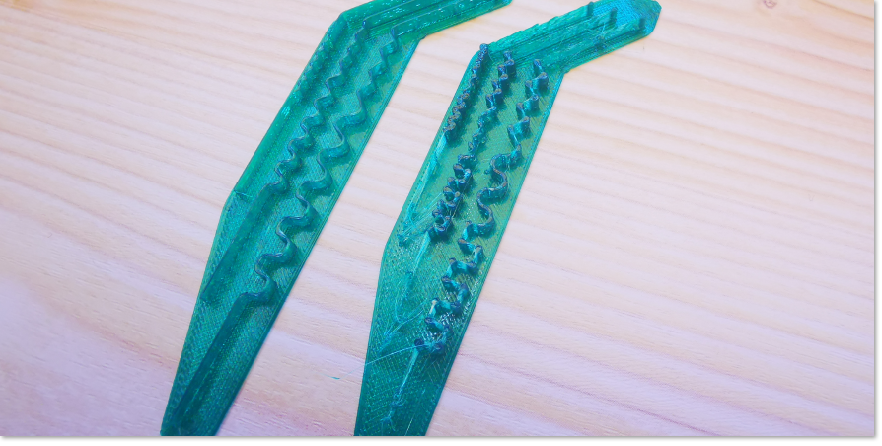
Using the Adaptive PA feature in Orca, I got the corners to appear clearly more like squares, but at the same time, the print showed stringing and seemed to have small defects, so not as clean as I would expect.
Inspecting the gcode file I noticed frequent M572 commands:
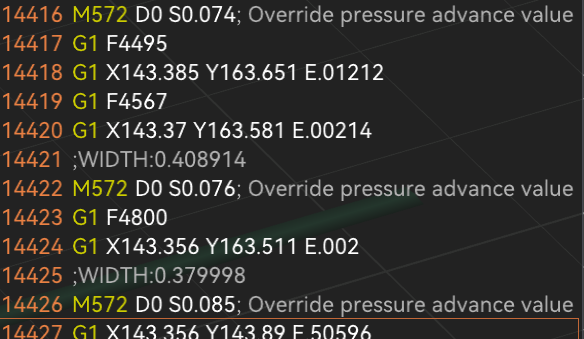
Looking at it while printing, I noticed that the print head was like stuttering. I soon realized that every M572 command issued was causing a small pause. If you look at the corners, where PA changes take place, they look like there is a blob there.
Then I did a simulation in DWC, but no pauses there. So this pauses did not come from the gcode.
After some research, I found the following note:
"Now start the print with pressure advance disabled. After a few layers enable pressure advance by sending the M572 command with your desired starting amount in the gcode console. You may notice a brief pause in movement while the value changes."
in the Duet3D Pressure Advance description:
Pressure advanceIn short, using Adaptive PA has a serious drawback of print quality, the contrary as it should be.
My questions:
Is there a way to implement Adaptive PA in firmware? Is there a command for that or is it planned?
Is there a workaround to avoid pausing at every change of the PA value due to the M572 command?Note:
I did not do any special calibration to gather a set of PA values for different speeds and accelerations.
I just used the formula (roughly):
Adapted PA value=Measured PA value * (measurement-speed/current speed)So this is not rocket science. Should be readily possible in firmware.
-
@Triet there are two reasons why frequent M572 commands won't work well with RRF:
- RRF waits for motion to stop when processing M572. This is to avoid issue if other input channels are modifying the machine configuration concurrently.
- If it didn't wait for motion to stop, there would still be a problem, because the new PA value would be applied to moves already in the motion queue that haven't been committed yet.
Nonlinear PA implemented in firmware would be a much better solution, if we can determine how PA should vary with extrusion speed and perhaps also with acceleration. The current formula is:
pressure_advance_distance = Ka * extrusion_speedSimplest would be to add a square term:
pressure_advance_distance = Ka * extrusion_speed + Kb * extrusion_speed ^2which in effect increases or reduces the PA constant linearly with speed. However, I'm not at all sure that this would meet the requirement, in particular if you set Kb to be negative so as to reduce the effective PA at high speeds, then this would cause PA to become negative at very high speeds. Maybe we should apply this formula only up to its peak value and then stay with the peak value at higher speeds.
Your suggestion is equivalent to doing this:
pressure_advance_distance = Ka * measurement_speedwhich doesn't look right at all to me, because it implies a pressure advance distance at zero speed.
Do you have any measurements to indicate how the ideal PA value for your hot end/filament combination varies with extrusion speed?
-
@dc42 this is the commit to orcaslicer for adaptive PA if thats any help https://github.com/SoftFever/OrcaSlicer/pull/5609
closed Enhancement: Adaptive Pressure advance #5609
-
@dc42 First of all, let me explain more precisely how I calculated the fictive PA values. I did this because this is a proof-of-concept for me, and in order to gather those values from real tests many tests are needed; the recommendation is to use at least three speeds at three different accelerations, so a minimum of nine measurements.
Still, the proof-of-concept worked, as I can confirm the enthusiastic reports of users even with these "fake" values.
The exact formula I used was:
Adapted_PA=MIN(nominal_PA * SQUAREROOT(speed-of-nominal-PA-measurement / current_speed); MIN_VALUE)This is the gradient I get (for a given acceleration of 5000mm/s2):
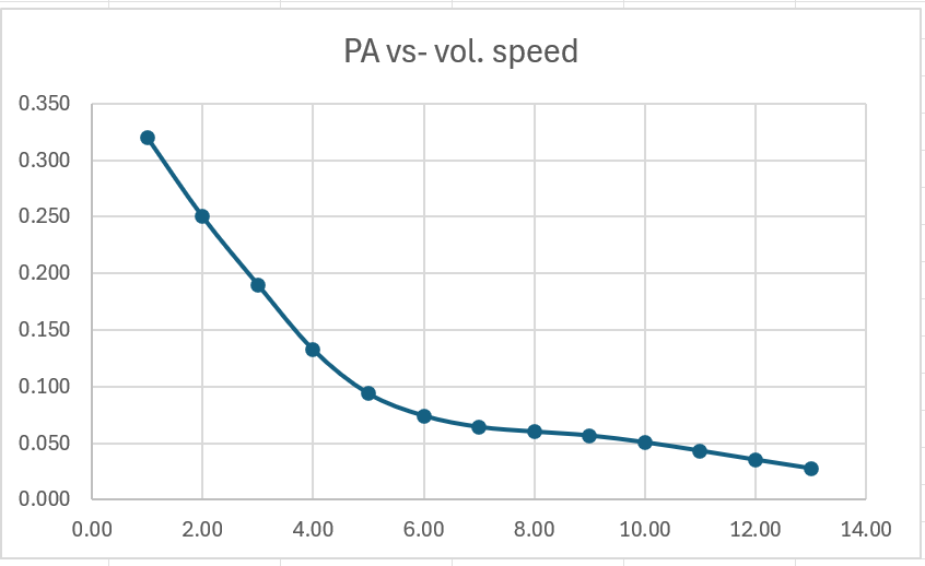
Note: the increase of PA at lower speeds gets very steep if no minimum value is defined.
Let me pick-up your key statement:
"Nonlinear PA implemented in firmware would be a much better solution, if we can determine how PA should vary with extrusion speed and perhaps also with acceleration. "No doubt at all. Slicer developers are shooting beyond their lines, but this is caused by missing solutions at the firmware level.
Let me mention that Klipper has also undertaken a similar, albeit simplistic and almost naive approach in this question.
I don't think following Klipper macro is official part of the firmware, but it has been successfully used:[gcode_macro G1] rename_existing: G99999 gcode: {% set p=[] %} {% for key in params %} {% set p = p.append(key + params[key]) %} {% endfor %} {% if params.F is defined %} {% set speed = params.F|int/60 %} {% set orig_pa = printer.configfile.settings.extruder.pressure_advance|float %} {% set pa = ([orig_pa * ( 100 / speed ), orig_pa]|min) %} #limit PA to max of original value. Better to have lower PA than higher due to underextrusion. SET_PRESSURE_ADVANCE ADVANCE={pa} {% endif %} G99999 { p|join(" ") }See this if interested:
Pressure advance becomes way too aggressive when speed is increased, but only on deceleration. Is an exponential variable neededI am virtually agnostic of Klipper macros, but even me could understand that (it assumes that the original PA value was determined at 100mm/s).
I am trying to make clear that non-linear PA is getting more and more imperative as 3D printers appear in the market, which are more capable and run at above 350mm/s or 30mm3/s, while they still must be able to print some regions slowly, and they must then transition between different speed/accel regimes without artifacts.
Now let's address the essential question, how to model that dependency. I have done some research and came to an astounding conclusion: I am convinced that no physical model would approriately cover all possible cases, not even a significant part of them. What I did with my simple fake "model" is only possible because I am casually covering a speed range up to 200 mm/s or 16mm3/s (for a 0.4 nozzle) where coincidentially this dependency can be described that way - in most cases. I was lucky. But with really high speeds above 300mm/s the PA trend might be inverted. For some materials PA goes up and down... it is completely unpredictable. You will certainly not implement firmware features based on luck.
What would be the solution then?
In any case, none that would hard code that dependency. I can depict two possibilities.1- The "empirical" one. This is what has been done in Orca. You put your values in there and an interpolation (PCHIP) is done. You don't have to care about understanding the underlying factors. Big disadvantage: You need to conduct a relatively high number of calibrations to gather the PA values. This seems trivial, but in practice that is the reason only few users are actually using Adaptive PA. If you change your hotend - you have to repeat the measurements!
2- The analytical one. Let the user calculate that dependency and use some parameters to fit it to the real values. But how? What is the formulat? I said there would be no universal formula reflecting the physics. At this point I would propose something that could turn out to be a sparkling idea: Let the user define that dependency too! I am not prepared to describe this in detail, but I think it should be possible. Perhaps a polynom with higher degrees and variable number of terms. May I recall the way non-linear extrusion is handled in RRF? (There, much to my regret , no fixed term is possible and the formula assumes that the characteristic curve passes through zero - it is too simple and hard-coded).
Still, the necessity to implement this in the firmware holds true.
To answer your question: Yes, I am planning to gather those values. More out of curiosity than seriously trying to use them as a sound model - I am constantly tinkering and they will change for sure. I can publish them here if wished but I would not do any deduction of general validity from what I find.
By the way, for Prusa slicer users, there seems to be an all-at-once (multiple) PA test available (recently published):
Adaptive Pressure advance for Prusa mini+Thanks for your attention.
-
You might take a look at this post-processing script for Superslicer/Prusaslicer:
Adaptive-Pressure-AdvanceThe author himself remarks there:
"Changing pressure advance on the fly seems to do some funky stuff"

Here is an in-depth discussion of questions related to non-linear PA (strongly recommended for the savvy people):
Regression in dynamic PAThere, the Orca developer elucidates the disadvantages of implementing Adaptive PA in the slicer, compared to firmware. Lots of insights. You will find some measurements too.
Some more measurements:
Modification of Pressure Advance for high speed Bowden printersI am afraid that the impact to quality caused by a pause introduced during a PA change could be exacerbated when using extrusion rate smoothing in the slicer, as this generates a number of consecutive segments. In my test above, I disabled this feature to keep things simple.
-
@Triet I've created a feature request on Github for this: https://github.com/Duet3D/RepRapFirmware/issues/1104
Ian
-
@droftarts Great!

