Like Z Banding
-
@Ce72 Most likely is that the thermal pad's thermistor is too close to the heating element, so reads higher than the rest of the bed surface when the heater is on (localised hotter temperature), then cools quicker than expected as heat dissipates through the bed. This tends to make the heating cycles shorter as they go on, causing the inconsistent behaviour, and long tuning cycle.
However, the tuning numbers you're getting are all pretty close, I'd think choosing the median for each parameter would be fine. If it triggers heater errors when heating normally, you can manually adjust it, see https://docs.duet3d.com/User_manual/Connecting_hardware/Heaters_tuning#manual-adjustments-to-the-heater-model-parameters
Ian
-
Hi Ian thank you for pointing me in the right direction to set the PID tune.
Then I run some tests to see If the banding had finally gone, unfortunately not so I decided to run some other tests to see if I could isolate the problem or ever just work out what effects the banding pattern.
This is the first test print after changing the heater and SSR as well as retuning the extruder PID. banding is the same as before.
The next test I turned off the bed heater after the first couple of layers. To see if the banding was being affected by the bang-bang theory being caused by the bed heater but the banding was still the same. This left me wondering if it was a back to a mechanical issue the good old Z wobble as nothing electrical or extruder seemed to be affecting the outcome.
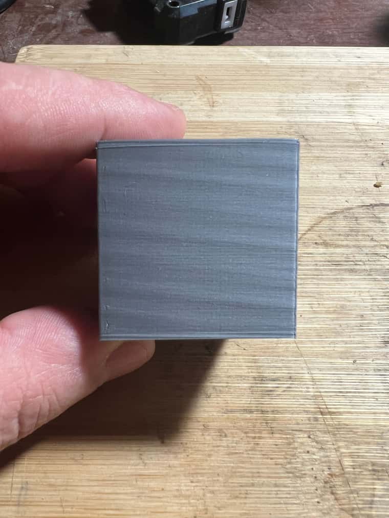
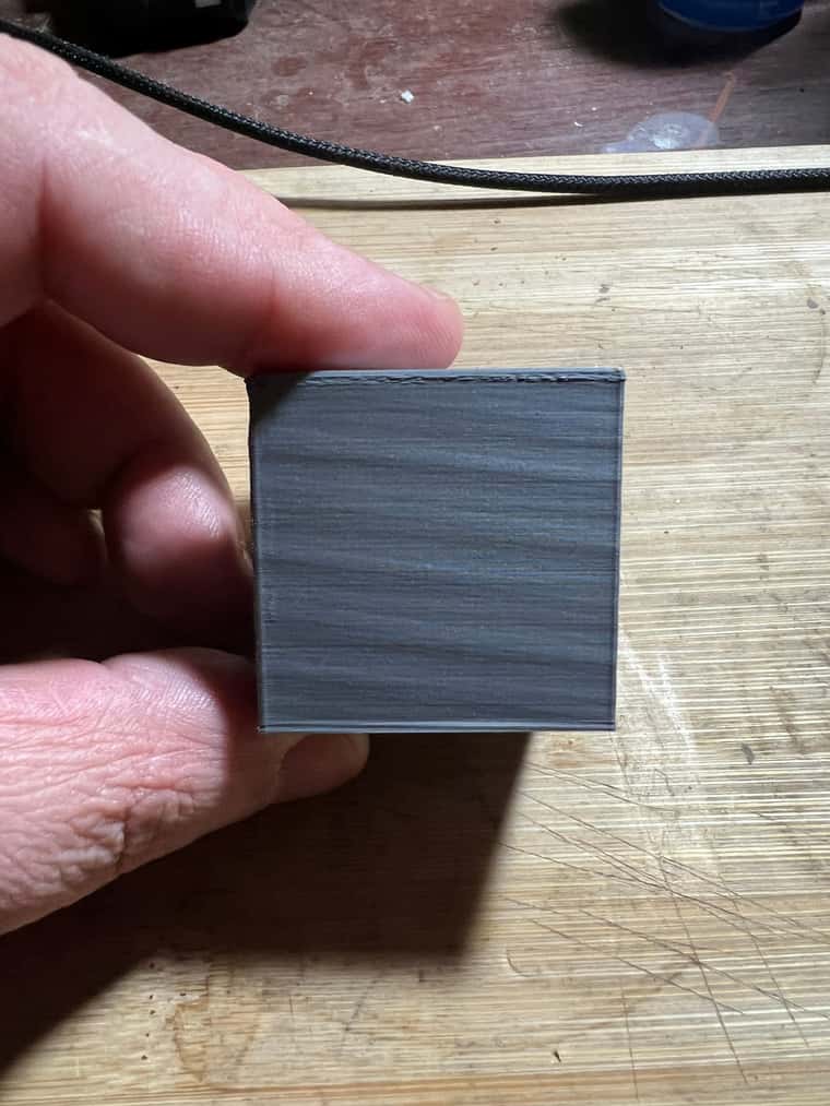
The last test I did after reimaging the pi (hey try anything at this point ) This time I resized the test model from a 40mm cube the a 80mm square by 25mm high same slicing profile as before but this time the banding was a lot closer together than before, To me me this eliminates a mechanical problem as the pattern frequence is so far away from the ball screw pitch.
As mentioned earlier in this thread I have also tried a diffent slicer, so it’s also not that
 I’m running out of things to try so any further suggestions from anyonre would be greatly appreciated
And sorry for the long post. -
@Ce72 Just to eliminate it as a possibility can you turn of Pressure Advance to see if there is any effect.
-
@tas Hi, Here's the result of of No PA
-
I'm inclined to think it's a mechanical issue either in the extruder or Z axis.
-
Here's a wild theory - there's some interaction between the bed heater and the extruder heater, such that when the bed heater turns on, the power to the extruder heater is reduced slightly, leading to small variations in the flow of plastic. If the duty cycle on the bed heater is regular, it could lead to a regular pattern in the output.
It seems unlikely because the relay you pictured shows your bed is heated by AC. But maybe something on the control side is sinking too much current.
You could test by monitoring the voltage and duty cycle to the extruder heater.
-
@mikeabuilder Hi, Thank you for your thoughts, but after going down the rabbit hole replacing the SSR and bed heater, I tried running a test print with the bed heater turned off to try and eliminate the bed heater and I still had the same results. but I'm not that clued up on electrics to know if that would negate any effects.
-
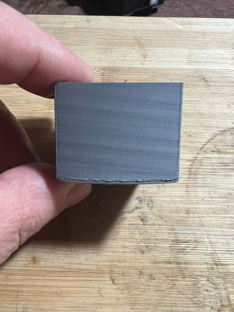
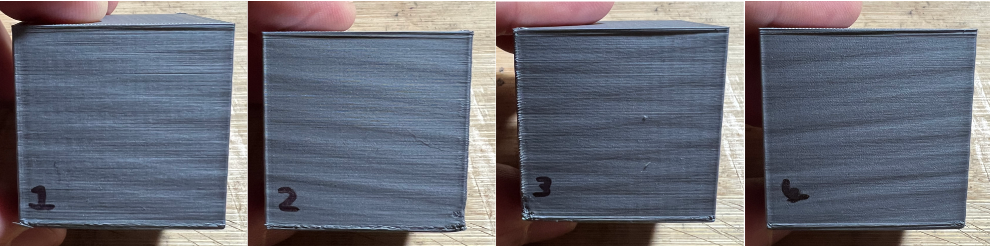
@Ce72 Hi, thank you for your input and any suggested test are much appreciated. I have tried changing the extruder gears and that unfortunatly had no effect, as for z wobble I would have thought the pattern would be the same on all faces, but what I have noticed is that the pattern changes direction and not on opposite face so it just adds to my confusion
-
@Ce72 Are these printed square to the XY axis? If so, try printing at 45 degrees to XY. As your printer is a core XY, this isolates the movement of each motor. As it seems to change direction depending on which side it's on, I'd guess that it's actually something to do with either the X or Y axis. How are the second motors on each of the X and Y axes wired? Are they wired in series (or parallel) with each other, so each axis is running from one stepper driver, or is each XY motor wired to it's own stepper driver?
Check all stepper motor pulleys are not moving on the stepper motor shaft, and that all motors are actually moving under power (ie no cabling issues). All motors should be exactly the same. Maybe post your config.g, and response to M122.
Ian
-
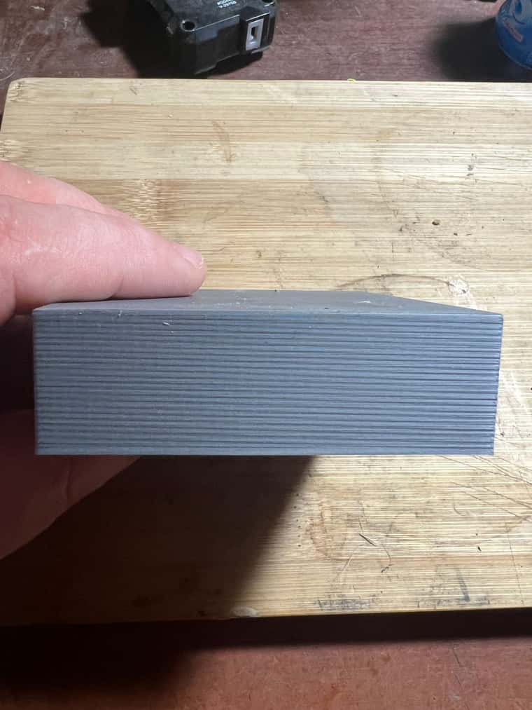
If you're going to print more tests, you could make an 8-sided box to enable looking at X-axis, Y-axis, and also each motor separately. You might also make that shape a "stepped pyramid" to be able to see if artifacts are starting at the corner (which might imply something to do with print head acceleration or extrusion speed). Your pictures posted on 16 Fed look like they have a very slight step at the bottom of the part, which gave me this idea.
Other thoughts after looking at the picture of the printer posted on 11 Feb...
Is there anything other than the shaft couplers preventing vertical motion of your Z lead screws? On my printer, I had some issues with z-banding and I switched from couplers like those you are using to the spring kind (which allows more Z movement). Then I put a screw collar (https://www.amazon.com/Shaft-Collar-Aluminum-Thickness-Screws/dp/B0BNZ937MV) on each z-shaft and put a thrust bearing (https://www.amazon.com/uxcell-F8-16M-Miniature-Bearings-8x16x5mm/dp/B07QLTXJDH) between that the the top of the lower bearing. Finally, I designed a spring loaded thing to put above the top of the shaft and keep a downward force on it. That cleaned up my z-banding.
On another printer, I had an issue where the threaded z shafts were not perfectly straight and they were moving the cars on the Z tracks slightly (again, z-banding). On this printer, I added oldham couplings (https://www.amazon.com/2-Pack-Coupling-Couplers-Compatible-Printer/dp/B0B17QWTG2) between the lead screw nut and the bed supports. It looks like you've maybe got something equivalent there. If so, these would isolate shaft wobble., but you might look for anything else that might be applying a force to the bed supports or the bed itself. It looks like there's a cable that may be tie-wrapped to the rear 2020 bed support. Better to tie wrap that the the lead-screw nut below the wobble decoupler. Any forces it applies will be isolated by the wobble-decoupler. The wiring from there to the bed would them have constant forces.
I think I might also be seeing a spring for a bed leveler on the right front corner (hard to tell for sure in the picture. If there isn't a hard connection for leveling (meaning the spring is holding it in place), that's another possible place for movement to happen if there are small irregular forces on the bed assembly.
Another thing to thing about is how rigid the print head is on the slider on the bridge. If there is any "play" in the slider, then the cables going to the print head might be wiggling the print head. If the extruder is "far" from the slider, it will amplify tiny movements.