Spirograph emulator with Duet2
-
@mrehorstdmd said in Spirograph emulator with Duet2:
What are you actually trying to do?
Good question.
If it's confirmed that Sandify's polar code is supported by RRF, I'd like to build a polar laser engraver or light grinder. (infinite rotation required and supported?)
It's definitely a step up and even easier to build than the SCARA-like dual arm, shown in my opening post.
I spent the whole Sunday afternoon watching your Arrakis playlist and then played with the polar version of Sandify. I created some interesting and doable patterns. Even some basic wiper pattern have their charm.
The fractal spirograph algorythm doesn't seem to produce the same patterns as the original, but much more complex and mesmerizing images. -
I've generated a testfile with Sandify for a polar machine. But the file looks like classic cartesian coordinates with 0,0 at the bottom/left end instead of center.
Is RRF able to digest that on a polar bed?<edit> according to the Wiki XY-offset is not supported yet
Is it possible to use a G1.1 macro instead which does the post processing on the fly?; ; File name: 'PolarSandify' ; File type: gcode ; G1 X117.776 Y111.451 G1 X87.768 Y122.172 G1 X67.855 Y95.324 G1 X88.664 Y67.022 G1 X123.451 Y78.957 G1 X122.412 Y117.191 G1 X84.209 Y127.838 G1 X62.033 Y93.102 G1 X89.794 Y60.376 G1 X130.841 Y77.746 G1 X126.383 Y123.577 G1 X79.901 Y133.128 G1 X56.414 Y90.128 G1 X91.762 Y53.782 G1 X138.485 Y77.431 G1 X129.625 Y130.544 G1 X74.879 Y137.970 G1 X51.070 Y86.420 G1 X94.566 Y47.321 G1 X146.295 Y78.037 G1 X132.081 Y138.024 G1 X69.184 Y142.294 G1 X46.072 Y82.003 G1 X98.194 Y41.072 G1 X154.184 Y79.584 G1 X133.701 Y145.943 G1 X62.864 Y146.034 G1 X41.488 Y76.908 G1 X102.629 Y35.115 G1 X162.063 Y82.081 G1 X134.440 Y154.223 G1 X55.972 Y149.130 G1 X37.386 Y71.172 G1 X107.846 Y29.527 G1 X169.842 Y85.534 G1 X134.258 Y162.782 G1 X48.566 Y151.522 G1 X33.828 Y64.837 G1 X113.815 Y24.386 G1 X177.429 Y89.936 G1 X133.125 Y171.536 G1 X40.709 Y153.160 G1 X30.874 Y57.950 G1 X120.498 Y19.763 G1 X184.735 Y95.276 G1 X131.016 Y180.395 G1 X32.470 Y153.995 G1 X28.579 Y50.565 G1 X127.851 Y15.730 G1 X191.671 Y101.533 -
@o_lampe said in Spirograph emulator with Duet2:
according to the Wiki XY-offset is not supported yet
For polar kinematics, that is correct. However, you can use workplace coordinate offsets to adjust the position. See the G10 command with the L2 or L20 parameter.
-
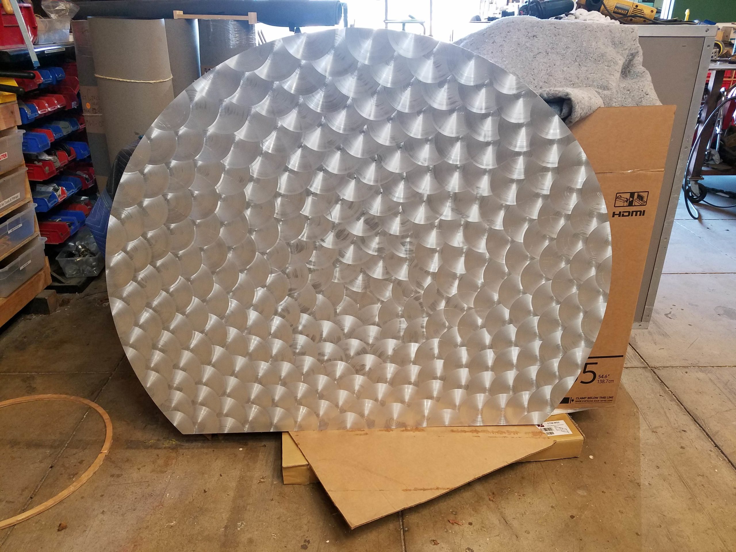
@o_lampe I've been thinking about building a machine that uses the sandify generated patterns to move a spinning abrasive head to do fancy engine-turning on metals.
You can export the sandify patterns in different formats:
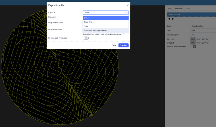
-
@mrehorstdmd My understanding is, when using polar printer kinematics, RRF internally converts regular gcode (XY based moves) into theta/rho values.
Brushed metal always looks great, but wouldn't it kill the brush, when it moves sideways while pressed on the sheet?
Guess what?!
My Boss has seen your Arrakis videos and now I have to build a sand table first
-
@o_lampe I would build the machine and alter the sandify patterns using a post processor, to press the spinning abrasive down and lift it up again at specified or calculated distances as it follows the pattern. But, it might also be create an interesting finish to drag it around while it is spinning against the metal.
There are abrasive "sticks" made for engine turning operations that wear away as they are used. They provide a consistent scratch size by controlling the diameter of the diamonds or other abrasive stones embedded in the stick. See: https://www.cratex.com/engine-turning-sticks
Are you going to use servomotors or steppers?
-
@mrehorstdmd said in Spirograph emulator with Duet2:
Are you going to use servomotors or steppers?
For the sand table my Boss donored a 60x40 window panel. It's the double walled/vacuum type.
I drilled a hole between the glass sheets and could fit a10mm steelball.
With a size like that, I guess steppers will do.
Fitting LED strips will be like building a bottle-ship, but without illumination it'll look dull.When I build an engraving polar machine later, it'll need strong motors. I think I use my favoured hoverboard BLDC motor with simpleFOCs step/dir interface.
-
@mrehorstdmd
I got 1kg of baking soda, but before I fill it in I want to know if I have to take any precautions.
What about air humidity?
Is static charge a problem?TIA
Olaf -
Maestro with M150 LED strips?
Another issue, I couldn't find answers yet. I want to use a Maestro board for the sand table, but couldn't find any info.
Is it the same NeoPixel/WS2812 pin as Duet2?
How many LEDs can I address? -
@o_lampe please be aware that we have stopped developing firmware for the Maestro, and there has never been official support for WS1812 or similar LEDs on the Maestro.
Duet WiFi hardware designer and firmware engineer
Please do not ask me for Duet support via PM or email, use the forum
http://www.escher3d.com, https://miscsolutions.wordpress.com -
@dc42 Too bad, but understandable.
If I had more knowledge of the whole compiling stuff, I'd probably build a FW-version with only CoreXY support. No extruders, fans or z-probe stuff to free as much RAM as possible.I guess, I have to digg deeper in my HW-grave. IIRC I still have a FLY super8 with burnt bed heater FET.
-
@o_lampe Are you planning to put the sand and ball between the two glass sheets? That's going to be a problem for spreading the sand. Also with narrow spacing, you can expect some of the sand to stick to the top glass from static charges. You really want to be able to clean the top glass, by lifting it up or removing it completely. Also, if you put LED strips in a narrow space at the level of the ball/sand, the sand will end up blocking the light. I think you really want to have 50 mm or so between the two sheets of glass, and the LED strips should sit about 10-20 mm above the level of the bottom glass.
A steel ball rolling on glass is surprisingly noisy. I used a fake leather white vinyl cloth to cover the bottom of the table to reduce the noise, and to always leave the bottom of the grooves drawn in the sand white. I also use an air gap between the magnet and the bottom glass to prevent noise from the magnet dragging on the glass.
I use RGB LED strips that allow color changes, and typically operate with two different colors because I like the contrast, but white all around also looks pretty good and long as the illumination angle is low so the ridges in the sand cast shadows. A lot of people use addressable LEDs and create all sorts of light shows, but I find I want to watch the ball drawing in the sand and flashing lights quickly become hard to look at.
Humidity isn't usually a problem with baking soda. I find that if I don't run the table for a couple weeks, small lumps will start to form, but they crumble to dust the instant the ball runs again.
I'm probably going to end up building a new coffee table because I don't think my brother is going to give me the old one back. I will buy a glass top table at a thrift store, and then either modify the table or throw the table away and use the top for the top glass on the sand table. I'm going to try using dibond material for the bottom of the table- it's a lot lighter and cheaper than glass (custom sized glass), it's rigid, and I can cut it to the size I need. I'm not sure if it will create drag because of eddy currents generated in the aluminum by the moving magnet- it shouldn't matter at low speeds, but high speeds?
-
@mrehorstdmd Thank you for the detailed answer.
I also have concerns about filling the soda between the glass sheets, but it was my Bosses idea, so I stick with it for now.
I also like the challenge to put LED strips in there, may it be useful or not.
We learn more from mistakes is the motto.
I'm with you about the Disco light show. Illumination should be tasteful and decent. That's why I picked addressable LEDs. I hope to find colours that match the sand theme. Blue/green on one side and red/orange on the other. Like a sunrise at the beach. -
@o_lampe RGB light strips can do color combinations like that without going to the trouble and extra expense of using addressable LEDs. I use something similar to this. It has two outputs for RGB LED strips wired in parallel - i.e. same color.
The 4 wire connections to the LEDs are R,G,B, and common. If you swap any two of the RGB wires on one of the connectors, you'll always have two different colors on the LED strips, unless you select white on the remote control- then all the LEDs in both strips light up and you get sort of white light. If you want the light show you can put the controller into a switching or fading mode and it will shift the colors of the LED strips.One of the things that happens on the table is the sand gets pushed toward the edges as the table runs and you periodically have to push it back toward the center of the table. That's going to be very difficult if the two pieces of glass are glued together and only a few mm apart. Also, as the ball rolls over an area multiple times, the surface it's rolling on becomes visible. In your case, it's glass so it will become transparent and you'll see through the bottom of the table.
-
@mrehorstdmd said in Spirograph emulator with Duet2:
you periodically have to push it back toward the center of the table. That's going to be very difficult if the two pieces of glass are glued together and only a few mm apart
I already filled the glass-gap with 1/3 Soda and started to even out the layer. The small gap between ball and upper glass was actually helpful: I could attract it with a second magnet through the top and move it by hand. A separate comb/wiper would be better, but there's always a next time..
If things work out, I'll draw the first lines today, but only in the center area (~300x200mm) and this time I won't forget to take pictures

-
@o_lampe Maybe you can build in a magnetic comb that sits between the glass sheets and move it with magnets from the top side when needed, and leave it along an unlit edge when it isn't needed.
-
A question about an exotic kinematic: @JoergS5
Would it be possible to add a rotary tool to a CoreXY frame?
The idea is to put the magnet on a 10cm arm rotating around the tool carrier, because
I want to reach areas outside of the current print envelope.
To achieve that, I was thinking of a postprocessor which moves the arm in 90° steps, depending on the direction I want to extend. (+/- Y or +/- X)
But it would be much cooler if it was an inbuild feature.The other option would be quite expensive (for a side project). I'd have to build a frame much bigger than the glass, which means new alu-extrusion, linear rails and belts.
-
Another question is related to Meta commands/macros:
Is it possible to read out the total number of gcode files on the SD-card and run them randomly?
A macro call at the end of each gcode file would select the next... -
@o_lampe said in Spirograph emulator with Duet2:
Would it be possible to add a rotary tool to a CoreXY frame?
The current RRF firmware calculates tools as being vertical, non rotating, non moving, describable with fixed XYZ offets (mesh compensation, baby stepping, tool changer depend on this linear offsets, e.g.).
To avoid this limitations, the tool itself can be divided into a part like a moving/rotating axis and a fixed endpoint which can be dimension zero. With robotic kinematics, you simply add this additional axis to the chain. Forward kinematics is easy to calculate, but inverse kinematics (calculation from world coorinates back to motor positions) can be complicated. It depends on the implementation and axis positions whether it's complicated or not.
If you design your tool as a spheric design, so that some axes cross in one point with the axes before, the inverse calculation is easier. When you have a prototype and description, we can solve it together.
-
@o_lampe said in Spirograph emulator with Duet2:
Another question is related to Meta commands/macros:
What I got so far:
- I rename all the patterns with numbers
- I add a subdirectory for wiper/eraser patterns
- I choose the next pattern by a random generator and filter out nonexisting numbers with
if exists - after each pattern, I call a random wiper pattern and vice versa
That way I don't have to know the exact number of existing patterns