Clearpath SD servos moving at different speeds
-
When I'm at a loss, I always try to narrow down the cause. I your case, I would start refresh, remove all special components and start with Duet and the expansion board. Mesasure voltage. Then one motor, measuring, then adding the controller, then two motors, different variations. Sort of.
I see different possibilities: different motor properties (resistor etc.), electric contacts. You should find the reason by isolating the possibilities.
In
https://duet3d.dozuki.com/Wiki/Using_external_stepper_motor_drivers
was a comment not to use a specific 3 pin connector "The 3-pin pads on the Duet near to the stepper drivers are test pads...", maybe you have some wrong wiring similar to that. -
I am curious, what voltage is your power supply? I use a Teknic 75 VDC on my CNC router and a 48 VDC power supply on my corexy. I never checked the signal voltage on my Duet expansion board.
Did you remap the driver signal to the expansion board outputs? I didn’t and discovered the motors worked but didn’t respond to changes I made in Duet firmware.
I run my step resolution higher then 800, I have experimented with different settings and didn’t see any difference, never tried anything that low. I went with a setting that that provided a setting close to the numbers used with a stepper. If the step resolution is to high the motors don’t rotate enough to be noticeable. I thought the motors were bad. -
M569 P0 S1 ; Drive 0 goes forwards
M569 P1 S1 ; Drive 1 goes forwards
M569 P2 S1 ; Drive 2 goes forwards
M569 P3 S1 ; Drive 3 goes forwards
M569 P4 S1 ; Drive 4 goes forwards
M569 P5 R0 T1:1:0.5:1
M569 P5 R0 T1:1:0.5:1
M569 P5 R0 T1:1:0.5:1
M584 X5:6 Y7 Z0:1:2:3 E4Shouldn't the arguments in bold (P5) be changed to P6 and P7 respectively? Looks like the T parameters are only being applied to the first X driver.
Another data point, I use external drivers as well, my spec sheet for my drivers had a minimum pulse width of 250ns, but I had to give it a pulse width of 2000ns to get it to actually work properly and not drop steps, so maybe try increasing the T values past what you think is needed.
I checked my expansion board (same one you use) and my output was also around 3.8-4V. The actual component data sheet is here: http://www.ti.com.cn/cn/lit/ds/symlink/sn75als192.pdf
-
We have swapped cables, motors, driver channels and get the same performance out of each channel regardless of any other physical changes. The performance is also not necessarily repeatable exactly. If we move the axis one direction and then back to zero sometimes it is off by a little or alot.
It seems that the board is not supposed to actually shift the voltage of every channel like it says in the pdf so we will have to accomplish that another way. Hopefully this is the issue, seems to explain it if the 3.5v is only sometimes activating the opto-isolators.
-
The expansion break out board has buffers on to increase the voltage to work with 5V logic. that may not be to exactly 5V as the have losses. I need to test my EBOB to see what voltages I am actually getting.
-
We don't have a single channel that tests over 4v.
-
I am an Engineer with Teknic.
While I do not have any experience with the Duet controller I want to
clarify that the ClearPath logic inputs are rated for 5-24Vdc. If
the Duet controller is not capable of consistently meeting at least 5Vdc
then it is very possible you will see intermittent behavior from the
ClearPath.Please feel free to email us at support@teknic.com if anything comes up we
can help with.Best regards,
Mark D.
-
@philmeiklejohn, @adammikulis I have confirmed that the EBOB are not outputting a 5V differential signal so that is the cause of the issue. It appears that all out other users who need a differential signal have been using drivers that may state they need 5V but actually work with <5V and so this issue has not come up before. I will investigate this in more detail now and get back to you.
-
@philmeiklejohn, @adammikulis I have updated the documentation to remove the reference to level shifting to 5V.
Looking at the clearpath usermanual I see:
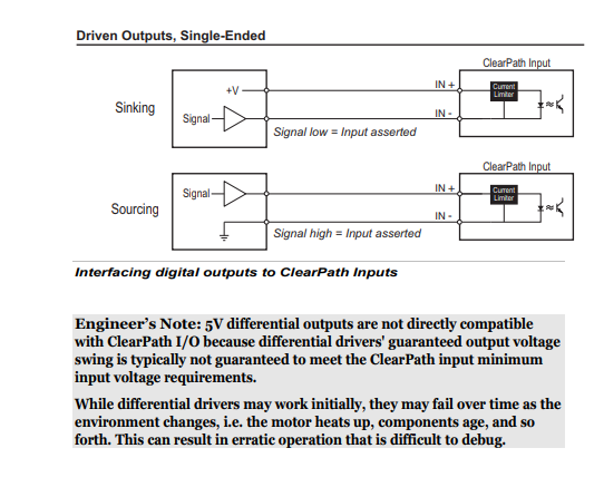
So It looks like the differential outputs of the EBOB are not ideal for driving the clearpath drivers.
As David said:
@dc42 said in Clearpath SD servos moving at different speeds:
AFAIR another user had a similar problem, and resolved it by increasing the T parameters in the M569 commands.
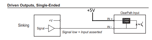
You can get a higher voltage to the opto isolators by connecting the + inputs of your drivers to +5V instead of to the + output terminals on the expansion board.
With that in mind it would be best to connect them in the sinking configuration with 5V provided to IN+ (adapted from drawing in from clearpath manual):
-
@nhof Good catch, it's actually correct in the config file but I was typing it from memory so I messed up those lines here. I will definitely try your suggestion and increase T even more than before, hopefully it won't miss any steps.
And regarding the voltage, if the expansion board isn't able to push 5V then could we simply use that level shifter I posted earlier to bump up each wire? Otherwise we may have to look at an entirely different control board since we need motors this powerful.
-
@adammikulis I think from what @Teknic_Servo have said means you should look at providing a +5V line and using the EBOB to switch the ground.
-
Excellent, seems to me the sinking method would be the simplest solution. We will give that a try.
-
This post is deleted!