FSR Controller Module for Auto Bed Leveling
-
Hi,
I wanted to share the FSR controller module for auto bed-leveling that I've designed to work specifically (but not exclusively) with the Duet.
Background
The initial inspiration for this mini-project came from JohnSL's excellent open-source project for this application.
At first I thought I'd experiment with the ready-made kit that's based on John's work and sold online commercially, but given the price-tag ($34.95 before shipping), I decided I'd rather make my own module with the exact specifications I'm looking for.
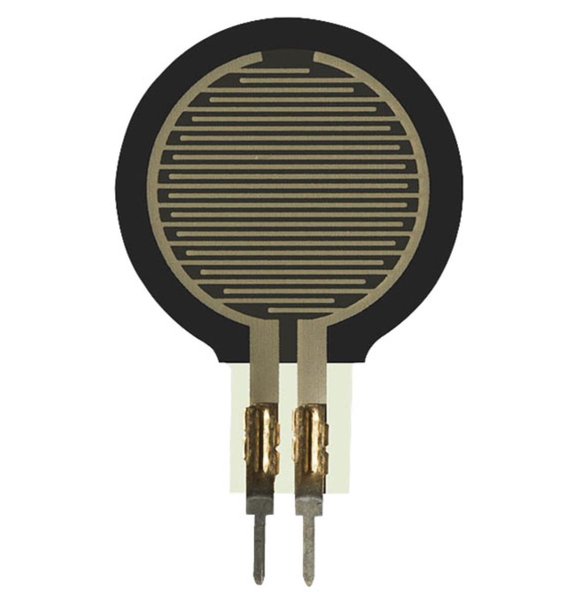
Both John's module and my own are designed to run 3 x FSRs (Force Sensitive Resistors) simultaneously, like the one shown below:

I got mine at RapidOnline, but they are readily available from numerous other suppliers, either with long or short leads.
The PCB dimensions of John's module and the one I made are also similar (though mine is slightly bigger), but that's where the similarities end as both the hardware and firmware are fundamentally different.
Design Considerations
I wanted to create a module that:
-
Can be seamlessly integrated with my Duet, but can also run in standalone mode (for testing and/or use in other, non-Duet machines).
-
Runs as fast and reliably as possible.
-
Has a minimal footprint.
-
Offers a convenient and easily accessible user interface, including onboard LEDs for indicating the initialization process and real-time sensor triggering.
-
Is able to automatically and quickly establish a baseline at startup against which to measure subsequent bed probes during the bed-leveling procedure.
-
Incorporates an adjustment mechanism for controlling the sensors' sensitivity level.
-
Can be reset manually to re-establish the measuring baseline.
-
Can be turned on (for bed-probing) or off (after the procedure is done).
-
Has an ICSP capability for bug fixes and/or future firmware updates.
-
Facilitates expandability to 6 x FSRs in case I'd like to go down that route at some point.
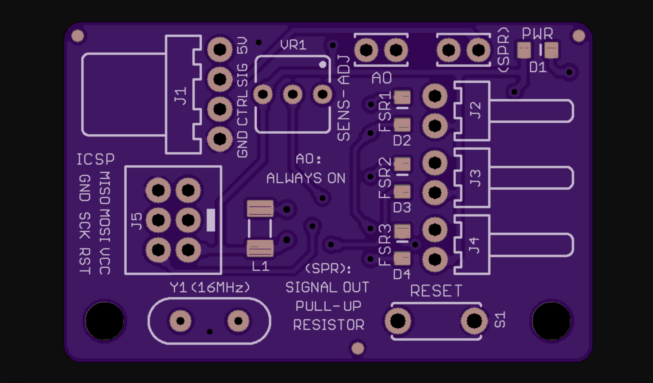
PCB
After some reading, head-scratching, and playing around with the PCB editor, I came up with the following design that covers all of the above:


Hardware Specs
-
5V Supply Voltage (I considered going with 3.3V like the Duet's logic, but in the end decided against it because I wanted the microcontroller to run at max speed)
-
Atmega328P-AU (smd version) @ 16MHz with an external crystal (for accurate timing)
-
ICSP header (for firmware updates/bug fixes)
-
Reset Button (for re-establishing the baseline for trigger measurements)
-
10K Trimmer (for manual sensitivity adjustment)
-
4 x LED indicators (1 x for power [green], and 3 x for each of the sensors [amber])
-
Signal Output - an Active-Low Open-Collector Combined signal for the 3 sensors (the signal is 5V, but is nevertheless compatible with the Duet interface via an onboard reversed diode).
-
An inductor/capacitor circuit for improved ADC readings of the sensors.
-
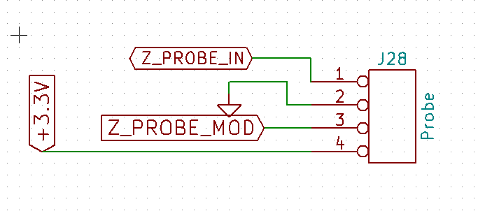
Control Input - for turning the module on/off via one of the Duet's I/O pins (see the Schematics pdf attached below for an example of how to turn the module on/off with the Duet).
-
Control Jumper - normally remains open, but can be closed to keep the module permanently on (for independent testing and/or use in other machines).
-
Pull-up resistor Jumper - normally remains open (as the Duet already has built-in pull-up resistors on its signal input pins), but can be closed for independent testing and/or use in other machines (essentially, closing this jumper converts the signal from open-collector type to a regular 5V/GND signal, but note that the signal is still Active-Low, i.e. 5V means none of the sensors is triggered, and GND means one or more are triggered)
-
Reversed Polarity Protection for the module's supply lines (by means of a P-channel mosfet).
-
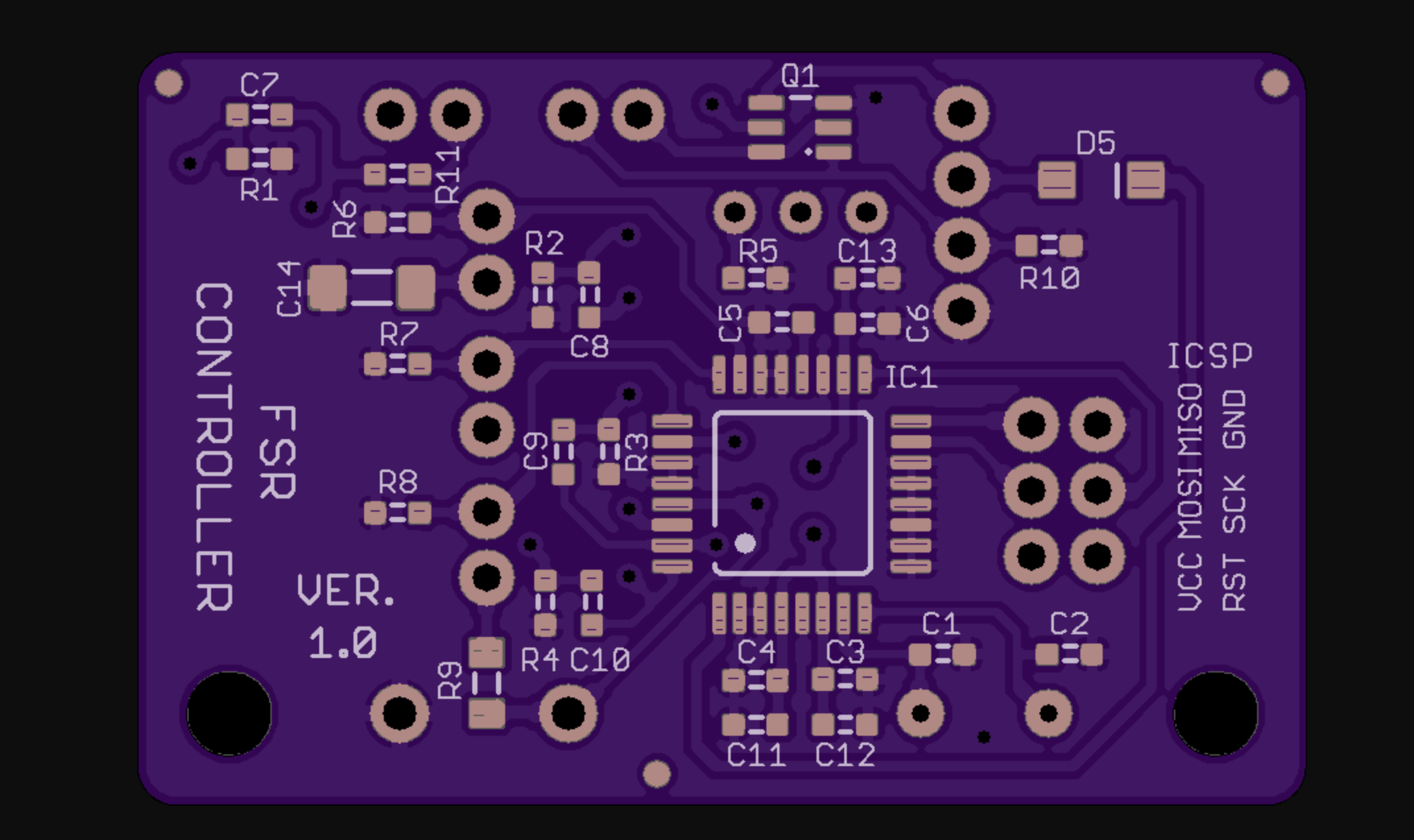
The PCB itself was designed with the free version of Eagle and manufactured by OSHPark.
Firmware Specs
-
Firmware was written in Arduino-Style C using the free Arduino IDE.
-
I've used the 'nano' bootloader - rather than the conventional bootloader for the Atmega328P - because the smd version of this chip has more I/O pins and thus requires an appropriate bootloader to run properly.
-
When turned on, the module runs a quick calibration procedure (about 2 seconds), in which it samples each of the sensors and establishes a 'baseline' average against which to check sensor triggering at runtime (this is a crucial feature for preventing false readings from the sensors as there will always be some initial pressure present (from the build-plate's weight if nothing else).
-
The initialization (or calibration) process is visually indicated by all amber sensor LEDs flashing 4 times, after which the module enters runtime mode.
-
During runtime, the output signal is pulled low and the relevant amber LED lights up whenever one of the sensors is triggered (two or more sensors can be triggered simultaneously).
-
If sensor triggering appears to be too sensitive or not sensitive enough, the 10K trimmer can be adjusted and then the reset button clicked so as to re-run the calibration process.
Open Source Design Files
Important Disclaimer: I've been working with electronics for a long time, but I am nevertheless a hobbyist and not a professional hardware engineer of any kind. I can therefore give no guaranty about the content of these files, apart from the mere fact that I've built the module and tested it myself. Hence, should you choose to use any of the following materials (or their derivatives), you must also be willing to take full responsibility for doing so.
fsr controller - schematics (pdf)
fsr controller - parts (Excel .xlsx)
fsr controller - firmware (Arduino .ino)
fsr controller - schematics (Eagle .sch)
fsr controller - schematics (Eagle .brd)
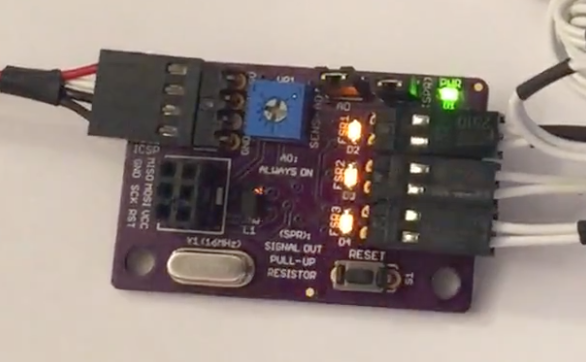
See It Live!
Here's a link to a short demonstration of the module in action
")
You'll notice that I click the 'reset' button on the module right at the beginning of the video - this is just to show the initial calibration process and isn't needed for normal operation.
Also, I haven't had a chance to install the module in my printer yet so there's still a lot of testing and potential firmware/hardware tweaking to be done, but given that many others have successfully implemented similar FSR architectures for bed-leveling (for example, see here), I'm hopeful this particular implementation would work out well too.
Should there be any interest, I'd be happy to report back on my progress with this, and of course, all comments/suggestions/corrections are always welcome
Thanks for reading,
SnowCrash -
-
Fantastic project and excellent writeup. I'm excited to follow along.
P.S. Re: Username. Stephenson rocks.
-
-
@snowcrash Yeah! great write up and application. I assume J1 is the output. What was the reasoning with not having that have same pinout as the Duet probe header?:
-
@t3p3tony said in FSR Controller Module for Auto Bed Leveling:
@snowcrash Yeah! great write up and application. I assume J1 is the output. What was the reasoning with not having that have same pinout as the Duet probe header?:
Thank you very much, @T3P3Tony!
J1 is indeed the output (or general I/O) of the module.
You're right that ideally the module would have had an identical pinout to that of the Duet header.
For the power lines, I considered using the 3V3 from the header, but eventually opted to go with the 5V provided by the adjacent header (Panel Due) as I'm not using it and wanted to have the Atmega328P's running at max speed (16MHz) which requires a 5V supply for the chip.
16MHz is almost certainly a total overkill and 8MHz would have most likely been more than enough for this application (though I haven't tested it in practice). Nevertheless, I figured it's a relatively easy tweak to switch from one supply to the other if the need arises, and the 5V supply was so close by I just couldn't resist
Regarding the z_probe_mod pin - that's a great point and a complete oversight on my part! I Thanks for bringing it to my attention! I read the description of that pin before, but for some reason, only the analog option stuck in my mind and I completely forgot it could have a digital output as well. If the z_mod_probe pin can be controlled with gcode like pin 50 on the expansion board, then it should definitely be used for the on/off control pin of the module.
Is it possible to use the M42 command to control this pin? And, if so, what would be its number?
M42 P? I0 - Turn module off M42 P? I1 - Turn module on Btw, is there a table/diagram mapping the all the hardware pins and corresponding software numbers?
-
@snowcrash said in FSR Controller Module for Auto Bed Leveling:
Btw, is there a table/diagram mapping the all the hardware pins and corresponding software numbers?
I think you are looking for Duet 2 Pinout Table?!
-
@wilriker said in FSR Controller Module for Auto Bed Leveling:
@snowcrash said in FSR Controller Module for Auto Bed Leveling:
Btw, is there a table/diagram mapping the all the hardware pins and corresponding software numbers?
I think you are looking for Duet 2 Pinout Table?!
Yep, thanks @wilriker!
This table would make me think I'm looking to use pin 34 (z_probe_mod), but then I looked up the original pin I was planning on using and came across something strange:
I was basing my original choice of pin 50 (CS5) on the documentation here, which has this table:

But the table you referred me to seems to have an entirely different designation for that pin (24 instead of 50):

What am I missing here?
-
@snowcrash said in FSR Controller Module for Auto Bed Leveling:
What am I missing here?
Aaaand that's the point where I am completely out again.
 I just remembered that I saw this table once but I have not yet really needed it, so no clue on why there exist different tables with different combinations of pins and numberings, sorry.
 -
@wilriker said in FSR Controller Module for Auto Bed Leveling:
@snowcrash said in FSR Controller Module for Auto Bed Leveling:
What am I missing here?
Aaaand that's the point where I am completely out again.
I just remembered that I saw this table once but I have not yet really needed it, so no clue on why there exist different tables with different combinations of pins and numberings, sorry.Ha! Thanks for sharing what you do know about this
@T3P3Tony, could you please help with the pin numbering in this context? especially, what numbers should I use to activate/deactivate pins 'z_probe_mod' and 'cs5' with M42 command's P parameter?
-
Looks like @T3P3Tony is busy.
Does anyone else knows the answer to the above question about the pin destination numbers?
-
-
@dc42 said in FSR Controller Module for Auto Bed Leveling:
See https://duet3d.dozuki.com/Wiki/Using_servos_and_controlling_unused_IO_pins.
Sorry, @dc42, but that's not really helpful - please read the last few posts and you'll see what I mean.
-
@snowcrash said in FSR Controller Module for Auto Bed Leveling:
@dc42 said in FSR Controller Module for Auto Bed Leveling:
See https://duet3d.dozuki.com/Wiki/Using_servos_and_controlling_unused_IO_pins.
Sorry, @dc42, but that's not really helpful - please read the last few posts and you'll see what I mean.
I added two rows to that table earlier today. You will be able to control the Z probe Mod pin via M42 in the next 2.01beta firmware, but bear in mind that it is driven automatically in some Z probe modes.
-
@dc42 said in FSR Controller Module for Auto Bed Leveling:
@snowcrash said in FSR Controller Module for Auto Bed Leveling:
@dc42 said in FSR Controller Module for Auto Bed Leveling:
See https://duet3d.dozuki.com/Wiki/Using_servos_and_controlling_unused_IO_pins.
Sorry, @dc42, but that's not really helpful - please read the last few posts and you'll see what I mean.
I added two rows to that table earlier today. You will be able to control the Z probe Mod pin via M42 in the next 2.01beta firmware, but bear in mind that it is driven automatically in some Z probe modes.
Thanks for this.
So, assuming I have version 2.01 of the firmware, I can use: M42 P60 S0/S1 to control pin CS5, and M42 P65 S0/S1 to control pin z_mod_probe? Is this correct?
-
@snowcrash said in FSR Controller Module for Auto Bed Leveling:
So, assuming I have version 2.01 of the firmware, I can use: M42 P60 S0/S1 to control pin CS5, and M42 P65 S0/S1 to control pin z_mod_probe? Is this correct?
Yes, but you will have to wait for 2.01beta3 to use M42 P65.