Fans not working
-
Hey Guys,
I just got my DuetWifi and none of the fans appear to be working. Neither of the always on fans or PWM controlled fans seem to work.
If I move the fan select jumper to the 5V setting the always on fan pins read correctly (at 5v), but I use 12v fans for everything so this does me no good..
I read this thread in my search for answers:
https://www.duet3d.com/forum/thread.php?id=4503#p39340In this thread it's suggested that:
You probably shorted out one of the fan connections or connected a fan with the black and red wires the wrong way round;, and that caused the trace between the VIN pin of the fan voltage selector jumper and +VIN on the power input terminal block to fuse. You can check that with a multimeter. If you find there is no continuity between those points, you can bypass that trace with a wire on the back of the board.
Can anyone clarify the second part of the comment for me?
I understand the word "fuse" to mean "connect", so if the Fan Jumper Select VIN pin has been fused with the +VIN terminal on the power in block… then I should see continuity between the two. But instead the comment suggests that if I do NOT see continuity between those points then I need to solder a wire to "bypass a trace". Maybe I have a misunderstanding with the terminology, but right now that seems contradictory - so I'd like some guidance.
To sum up I have three questions:
What should the voltage read on the "vFan Jumper Select" vin-pin be?
What pins should I be testing for continuity between in this scenario to test if something is messed up? (vfan select vin and power in vin?)
If I get a reading on this in contradiction to what it should be - what two pins should the wire jumper be between to bypass the issue?Thanks in advance for any help you can provide.
-
The verb "to fuse" has more than one meaning in English. One meaning is "to connect with a fuse". Another meaning is "to burn out due to excessive current" (which is what happens when a fuse blows). That's the meaning I intended in my reply. I suspect that part of the trace has burned out, and if that is the case it needs to be bypassed.
The pins to connect are the VIN pin on the fan voltage selection jumper block, and the + pin on the VIN power input terminal block. Use a multimeter to check whether there is continuity between these pins first - if there is, then the trace has not burned out.
HTH David
-
Thank you very much for clarifying that for me!
Based on your description I was able to test and confirmed that the trace between the vfan select and power in Vins had fused.
I temporarily connected a wire directly from an available 12v output on the PSU to the V_FAN pin on the fan select jumper block and the fans began to work again.
Out of curiosity is this a viable long term solution (if I have no interest in powering 5v fans)? Or would you recommend soldering a jumper directly from the Power In terminal to the VIn pin (and subsequently using the jumper)?
EDIT:
Saw my question answered in another thread. For anyone that finds this in the future; the answer is yes, you can connect 12v directly to the v_fan header of the Fan Select pin block to bypass a fused trace.
Thanks for your assistance!
-
I just had this same issue. I bought a Duet Wifi and set everything up this week but I couldn't get any of the fan pins to work right out of the box. All of the fans were wired up correctly and I was careful not to mess anything up while plugging everything in, so I don't see how anything could have shorted.
I checked for continuity between the 12v terminal and the VIN pin on the jumper block using a multimeter and that turned out to be the issue, and after connecting them with a wire the fans now turn on properly.
Very annoying, but at least it's an easy fix.
-
The latest PCB version (1.03) of the Duet WiFi/Ethernet has a fuse in series with that trace.
-
Ok, that's the blade fuse at the bottom of this page (https://duet3d.dozuki.com/Wiki/Connector_and_spare_part_numbers#Section_Blade_fuse) right? I'll remove the wire and check whether the fuse has gone.
Thanks for the help.
-
So my multimeter says there's about 0.9MΩ of resistance across the fuse. I think it's safe to say it's probably dead…
I'll order another one.
-
So what could be wrong if I still have continuity from the Fan Jumper Select VIN pin and the +VIN terminal on the power in block?
I've been very careful not to jump any wires and haven't seen any shorts yet.
I've also tried all the gcode commands regarding the fan. Still no go.
The fans just don't work. I tried all the fans I have both new and old so I'm sure it's not them. Any other ideas to would be greatly appreciated.
-
@spidy said in Fans not working:
So what could be wrong if I still have continuity from the Fan Jumper Select VIN pin and the +VIN terminal on the power in block?
I've been very careful not to jump any wires and haven't seen any shorts yet.
I've also tried all the gcode commands regarding the fan. Still no go.
The fans just don't work. I tried all the fans I have both new and old so I'm sure it's not them. Any other ideas to would be greatly appreciated.
Do the always-on fan outputs work, or not?
-
If the always-on fans work, the problem is blown fan mosfets. The fan mosfets will blow if the outputs are shorted or overloaded. In some cases they may also blow if the fan is connected the wrong way round.
-
If the always-on fans don't work, then either there is a burned-out trace, or the 1A fuse in 1.03 and later boards has blown, or the fan voltage select jumper is not fitted. With power off, check with a multimeter whether there is continuity between +VIN and the VIN end of the fan voltage select jumper, and between the centre pin of the fan voltage selector jumper and the VFAN pins of the fan outputs.
-
-
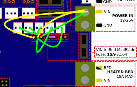
@dc42 Thanks for the tips but I still don't know what's going on! I did all the continuity test you said to do and if you look at the image, there's continuity in greens, no continuity in yellow and pink for the jumper on the board. My board says v1.2.

Also none of the fans work and I even changed them all not to be no Thermostatic control.
If it's a mosfet problem how do I confirm and fix it? Do I need to get a new board?
Thanks again for taking the time to answer my noob questions. Other my fan problem this thing is super quiet. I'm considering getting another to replace my CR-10 mini board

-
@dc42 - I checked mine for continuity and all shows they are working. What if the fan on Fan 0 (Fan 1 in the control panel) was working prior to upgrading the firmware from 1.17e to 1.19.2 but now that fan is not working at all ? However fan 1 & 2 is working, but you can't control them with the slider. I assume that makes since, anyhow this is the line in my config.g ; shouldn't the middle fan be working, and with the slider? Or do I have a hardware issue? Thanks
; Fans
; Fan 0 is used as the part cooling fan for tool 0 (see M563 in the Tools section above)
M106 P1 S1 I0 F500 H1 T45 ; Set fan 1 (hotend) value, PWM signal inversion and frequency. Thermostatic control is turned on.
; Fan 2 not connected -
@titanhusker said in Fans not working:
@dc42 - I checked mine for continuity and all shows they are working. What if the fan on Fan 0 (Fan 1 in the control panel) was working prior to upgrading the firmware from 1.17e to 1.19.2 but now that fan is not working at all ? However fan 1 & 2 is working, but you can't control them with the slider. I assume that makes since, anyhow this is the line in my config.g ; shouldn't the middle fan be working, and with the slider? Or do I have a hardware issue? Thanks
; Fans
; Fan 0 is used as the part cooling fan for tool 0 (see M563 in the Tools section above)
M106 P1 S1 I0 F500 H1 T45 ; Set fan 1 (hotend) value, PWM signal inversion and frequency. Thermostatic control is turned on.
; Fan 2 not connectedIf by the middle fan you mean Fan 1, then as you have configured it for thermostatic control, the slider will have limited effect on the speed, and only when the fan has turned on because heater 1 is at 45C or more.
More recent firmware and DWC versions provide more fan controls in DWC.
-
@spidy said in Fans not working:
@dc42 Thanks for the tips but I still don't know what's going on! I did all the continuity test you said to do and if you look at the image, there's continuity in greens, no continuity in yellow and pink for the jumper on the board. My board says v1.2.

Also none of the fans work and I even changed them all not to be no Thermostatic control.
If it's a mosfet problem how do I confirm and fix it? Do I need to get a new board?
Thanks again for taking the time to answer my noob questions. Other my fan problem this thing is super quiet. I'm considering getting another to replace my CR-10 mini board

Please confirm whether the always-on fan outputs are working or not. Perhaps you meant they are not working when you said "none of the fans work", but I want to be sure.
-
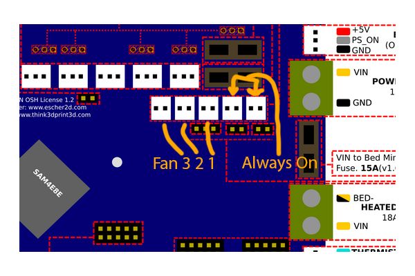
@dc42 - Well this setup has 1 fan (on the hot end heat sink) on the always on circuit, and another one for part cooling, according to the board layout diagram, it is position on fan 0, but never turns on. Even if the hot end is heated up past 45, I assume on the duet WiFi control panel it is considered fan 1, because only 1,2, &3 are options. If I change the coding to P2 and physically move the fan plug over to fan 1 on the board, the fan comes on, but there is not control over it to turn it off, for example when I print with abs. The slider doesn’t work, it is just always on. The short of it, Fan 0 (board)/Fan1 (Control Panel) doesn’t turn on, Fan 1(board)/Fan 2 (Control Panel) doesn’t turn off. I want to say on the continuity test, it shows 9v on all of +, I assume that means the circuit is not blown, correct?
-
@dc42 Both the always-on fans are not working. Just to confirm.
-
OK, does the same fan work if you connect it directly to VIN?
Do you have a jumper on the fan voltage selector block, between the centre and VIN pins? Have you tried another jumper?
-
@dc42 I moved the jumper to V_FAN and VIN it now works!
 Thanks! I guess the jumper was in the wrong place all along.
 -
@dc42 Not trying to take over @ spidy post....... But since I am experiencing something similar, I have been following along and my jumper is in the correct place, I followed the continuity test you recommended on this post and everything seems to check out, guessing it is a setting I am overlooking, is there something that doesn't seem right with this config for the fan to be working. Maybe the hard was is faulty? In Fan position 1, the fan does nothing at all, even if it set like this
; Fans
; Fan 0 is used as the part cooling fan for tool 0 (see M563 in the Tools section above)
M106 P1 S1 I0 F500 H1 T45 ; Set fan 1 (hotend) value, PWM signal inversion and frequency. Thermostatic control is turned on.
; Fan 2 not connected
; Fan 3 not connectedIf set like this
; Fans
; Fan 0 is used as the part cooling fan for tool 0 (see M563 in the Tools section above)
M106 P2 S1 I0 F500 H1 T45 ; Set fan 2 (hotend) value, PWM signal inversion and frequency. Thermostatic control is turned on.
; Fan 1 not connected
; Fan 3 not connectedThe Fan 2 position the fan turns on when hot end reaches 45C and turns off below that, above 45 though, you can not shut the fan off, even in the slicer. I need full control over it, for ABS prints. The slider in the control panel doesn't appear to control anything.

; Fans
; Fan 0 is used as the part cooling fan for tool 0 (see M563 in the Tools section above)
M106 P1 S1 I0 F500 H1 T45 ; Set fan 1 (hotend) value, PWM signal inversion and frequency. Thermostatic control is turned on.
; Fan 2 not connected
; Fan 3 not connectedThanks
-
@titanhusker said in Fans not working:
In Fan position 1, the fan does nothing at all, even if it set like this
; Fans
; Fan 0 is used as the part cooling fan for tool 0 (see M563 in the Tools section above)
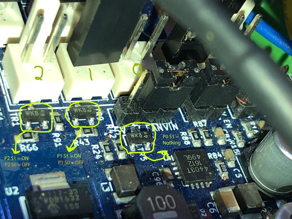
M106 P1 S1 I0 F500 H1 T45 ; Set fan 1 (hotend) value, PWM signal inversion and frequency. Thermostatic control is turned on.Does the fan turn on if you send M106 P1 S1 H-1 ? If it doesn't then the Fan1 mosfet has probably failed.
L If set like this
; Fans
; Fan 0 is used as the part cooling fan for tool 0 (see M563 in the Tools section above)
M106 P2 S1 I0 F500 H1 T45 ; Set fan 2 (hotend) value, PWM signal inversion and frequency. Thermostatic control is turned on.
; Fan 1 not connected
; Fan 3 not connected
The Fan 2 position the fan turns on when hot end reaches 45C and turns off below that, above 45 though, you can not shut the fan off, even in the slicer. I need full control over it, for ABS prints. The slider in the control panel doesn't appear to control anything.
It's intentional that you can't reduce the speed of a thermostatically-controlled fan to below 50%. If you stop cooling the heatsink, your hot end will jam.
-
@dc42 said in Fans not working:
M106 P1 S1 H-1
That command does work but for the port it is currently plugged into, I originally had it set up on the right on 0. So I assume that the P0 mosfet is bad; I guess I will jus keep it on on the one it is on, it is working. Thank you for helping me isolate the issue.
