Solved - Dead duet wifi board???
-
@dc42 said in Dead duet wifi board???:
I think you had a short in your external wiring between VSSA and a 12V or 24V component, which blew the VSSA fuse and also damaged the processor. On the 1.01 and later revision PCBs we changed the design to better protect the processor when this type of short occurs.
So I'm done? Even if i replace the fuse?
-
-
@dc42 my new board is on the mail right now, but i don't want to throw my bad duet to the trash... seems wrong!! so i've ordered a replacement processor to see if my skills are up to the task. apart of mad soldering skills, is there anithing special to do it?? like some really hard to find header to flash the new cpu?
-
The bootloader is in the ROM of the processor, so there's no special procedure to flash it for the first time. Just connect to USB and it should show up as Bossa Port.
In my experience, the trickiest part is removing the old processor without damaging the PCB. Here are 2 ways:
-
Remove the SD card from the Duet, put the Duet on an electric hotplate, and heat it to about 120C (I use a multimeter thermocouple probe between the Duet and the hot plate to monitor the temperature). Then use a hot air rework tool with a large square nozzle to heat the processor, and a vacuum pickup tool (very cheap on eBay) to remove it. Take care not to disturb the surrounding components, which will also be loose. Then use a no-clean flux pen to apply flux to the pads and the legs of the chip, and solder it back using hot air.
-
Use ChipQuik or similar very low melting point solder. After removing the processor, use solder wick to remove the low melting point solder from the pads, taking care not to pull the pads off the PCB. It's very brittle, so it's essential to remove it. Then use a fine tipped soldering iron to solder the pins. You will get some solder bridges, so use solder wick to remove them.
Duet WiFi hardware designer and firmware engineer
Please do not ask me for Duet support via PM or email, use the forum
http://www.escher3d.com, https://miscsolutions.wordpress.com -
-
@dc42 said in Dead duet wifi board???:
The bootloader is in the ROM of the processor, so there's no special procedure to flash it for the first time. Just connect to USB and it should show up as Bossa Port.
In my experience, the trickiest part is removing the old processor without damaging the PCB. Here are 2 ways:
-
Remove the SD card from the Duet, put the Duet on an electric hotplate, and heat it to about 120C (I use a multimeter thermocouple probe between the Duet and the hot plate to monitor the temperature). Then use a hot air rework tool with a large square nozzle to heat the processor, and a vacuum pickup tool (very cheap on eBay) to remove it. Take care not to disturb the surrounding components, which will also be loose. Then use a no-clean flux pen to apply flux to the pads and the legs of the chip, and solder it back using hot air.
-
Use ChipQuik or similar very low melting point solder. After removing the processor, use solder wick to remove the low melting point solder from the pads, taking care not to pull the pads off the PCB. It's very brittle, so it's essential to remove it. Then use a fine tipped soldering iron to solder the pins. You will get some solder bridges, so use solder wick to remove them.
Meanwhile my refurbished board is still in transit to my country, i've managed to replace the processor and add a MF-MSMF014 self resetting fuse. also added the 10K resistor between the TCK and VSSA pins, but when i run the M115 command the response from the board is:
FIRMWARE_NAME: RepRapFirmware for Duet 2 WiFi/Ethernet FIRMWARE_VERSION: 2.01(RTOS) ELECTRONICS: Duet WiFi 1.0 or 1.01 FIRMWARE_DATE: 2018-07-26b2
And not 1.02 as it's supposed to...
-
-
Where you have soldered the resistor to the TCK pin, are you sure that it isn't shorted to an adjacent pad?
Duet WiFi hardware designer and firmware engineer
Please do not ask me for Duet support via PM or email, use the forum
http://www.escher3d.com, https://miscsolutions.wordpress.com -
@dc42 said in Dead duet wifi board???:
Where you have soldered the resistor to the TCK pin, are you sure that it isn't shorted to an adjacent pad?
Yes, I've checked twice. No short to the adjacent pad.
-
Do you definitely have continuity between VSSA and GND, through the PTC fuse that you added? A few ohms resistance is normal. The PTC fuse may take a while to recover after you soldered it.
EDIT: to determine the board revision, the firmware enables the internal pullup resistor (value about 100k) on the TCK pin and then reads the input level on that pin. If it reads high then the firmware assumes that nothing is connected to that pin and the board revision is 1.0 or 1.01. If it reads low (because of the 10k resistor pulling it down to VSSA) then it assumes a 1.02 or later board.
Duet WiFi hardware designer and firmware engineer
Please do not ask me for Duet support via PM or email, use the forum
http://www.escher3d.com, https://miscsolutions.wordpress.com -
@dc42 said in Dead duet wifi board???:
Do you definitely have continuity between VSSA and GND, through the PTC fuse that you added? A few ohms resistance is normal. The PTC fuse may take a while to recover after you soldered it.
EDIT: to determine the board revision, the firmware enables the internal pullup resistor (value about 100k) on the TCK pin and then reads the input level on that pin. If it reads high then the firmware assumes that nothing is connected to that pin and the board revision is 1.0 or 1.01. If it reads low (because of the 10k resistor pulling it down to VSSA) then it assumes a 1.02 or later board.
Yes, I have continuity between VSSA and GND. The resistance through the PTC fuse in 1.9ohm.
It is normal to have continuity between the VSSA and TCK?
-
@celulari said in Dead duet wifi board???:
It is normal to have continuity between the VSSA and TCK?
Only via the 10K resistor that you added.
Duet WiFi hardware designer and firmware engineer
Please do not ask me for Duet support via PM or email, use the forum
http://www.escher3d.com, https://miscsolutions.wordpress.com -
@dc42 said in Dead duet wifi board???:
@celulari said in Dead duet wifi board???:
It is normal to have continuity between the VSSA and TCK?
Only via the 10K resistor that you added.
Oops... I have continuity even without the resistor... But it's printing

-
Any clues about what may be causing the short?
-
As TCK is right next to GND on the 2x5 pads where you connected the resistor, a solder bridge between those pads is the most likely explanation.
Duet WiFi hardware designer and firmware engineer
Please do not ask me for Duet support via PM or email, use the forum
http://www.escher3d.com, https://miscsolutions.wordpress.com -
@dc42 said in Dead duet wifi board???:
As TCK is right next to GND on the 2x5 pads where you connected the resistor, a solder bridge between those pads is the most likely explanation.
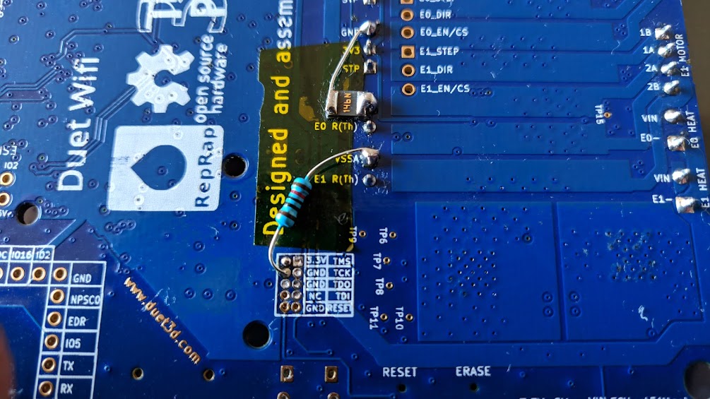
finally figured out!
i've followed the instructions on the wiki page https://duet3d.dozuki.com/Wiki/Connector_and_spare_part_numbers#VSSA_fuse for bypassing the fuse and add the 10K resistor, and solderd by this image on the wiki:
But!!! that picture is wrong!!!! the resistor is NOT going to the TCK, is connected to ground, as my board recently. The pad to the left is the TCK pad!
how do i know?
The proof...
So now my board is not dead, but upgraded!
The processor swap was relatively easy. if anyone wants more details, i've made a video of the process.
-
You are right, the labels next to the 2x5 pad array are wrong. The two columns should be swapped.
Duet WiFi hardware designer and firmware engineer
Please do not ask me for Duet support via PM or email, use the forum
http://www.escher3d.com, https://miscsolutions.wordpress.com -
@dc42 said in Dead duet wifi board???:
You are right, the labels next to the 2x5 pad array are wrong. The two columns should be swapped.
And the wiki should be updated
")
-
I already did that.
Duet WiFi hardware designer and firmware engineer
Please do not ask me for Duet support via PM or email, use the forum
http://www.escher3d.com, https://miscsolutions.wordpress.com -