Duet3D Logo Duet3D
    • Tags
    • Documentation
    • Order
    • Register
    • Login

    Configuring 12864 LCD on Maestro?

    Scheduled Pinned Locked Moved
    Duet Hardware and wiring
    20
    79
    23.5k
    Loading More Posts
    • Oldest to Newest
    • Newest to Oldest
    • Most Votes
    Reply
    • Reply as topic
    Log in to reply
    This topic has been deleted. Only users with topic management privileges can see it.
    • dc42undefined
      dc42 administrators @Agniusm
      last edited by

      @agniusm said in Configuring 12864 LCD on Maestro?:

      I am testing clone maestro before I get the real deal. I have ender 3 and it comes with 12864 lcd. Its different than is advised that it does not have sd card. It has 3 exp connectors. Exp3 matched pins on duet lcd but will it work with only one cable as I have menus on but lcd is blank? Would be good to get it working as that would save me some money as I need lcd's for 12 printers.

      The schematic is at https://github.com/T3P3/Duet/blob/master/Duet2/Duet2Maestro_v1.0/Duet2Maestro_Schematic_v1.0.pdf. The connections for the LCD are all on connector P2. Connector P1 carries the connections for the SD card (which you can leave out) and the ENC_A and ENC_B connections for the rotary encoder.

      Duet WiFi hardware designer and firmware engineer
      Please do not ask me for Duet support via PM or email, use the forum
      http://www.escher3d.com, https://miscsolutions.wordpress.com

      1 Reply Last reply Reply Quote 1
      • arnd13undefined
        arnd13 @Agniusm
        last edited by arnd13

        @Agniusm

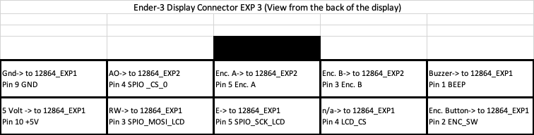
        I just got the Ender-3 display working with Duet Maestro running firmware 2.02RC5. You have to activate the display as described by dc42 with gcode M918 P1 E4
        (I used E4 because the response to the encoder was better).

        Here ist the wiring:
        0_1543808714518_24697c77-88a7-4999-9578-a28479e0d7ad-image.png

        Agniusmundefined 2 Replies Last reply Reply Quote 1
        • dc42undefined
          dc42 administrators
          last edited by

          Thanks! May I add your diagram to the wiki documentation?

          Duet WiFi hardware designer and firmware engineer
          Please do not ask me for Duet support via PM or email, use the forum
          http://www.escher3d.com, https://miscsolutions.wordpress.com

          deckingmanundefined arnd13undefined 2 Replies Last reply Reply Quote 0
          • Agniusmundefined
            Agniusm @arnd13
            last edited by Agniusm

            @arnd13 thought i read somewhere that command is not necessary, well, great news then.

            1 Reply Last reply Reply Quote 0
            • Agniusmundefined
              Agniusm @arnd13
              last edited by

              @arnd13
              Just tried wiring it according to your pinout and its still blank. I updated firmware to 2.02RC5.
              Does M918 goes to config.g?
              Where did you get your menu files? Should not make a difference bu still...

              1 Reply Last reply Reply Quote 0
              • deckingmanundefined
                deckingman @dc42
                last edited by

                @dc42 said in Configuring 12864 LCD on Maestro?:

                Thanks! May I add your diagram to the wiki documentation?

                Is that wise? Given that this is another clone? Can you be sure that the pinouts are the same as an original?

                Ian
                https://somei3deas.wordpress.com/
                https://www.youtube.com/@deckingman

                Agniusmundefined 1 Reply Last reply Reply Quote 0
                • Agniusmundefined
                  Agniusm @deckingman
                  last edited by

                  @deckingman said in Configuring 12864 LCD on Maestro?:

                  e same a

                  Mine is clone until i fry it and make it all good.
                  @arnd13 may have genuine, i dont know.

                  I have just made jumper wires and wend wire by wire but its still blank. It might be clone pinout as deckingman mentioned, have no clue.

                  1 Reply Last reply Reply Quote 0
                  • Agniusmundefined
                    Agniusm
                    last edited by

                    @dc42
                    I went poking wires all over and can confirm it is working now. Pinouts given by @arnd13 did not match. I have tested Reparapdiscount display which came in at the time i was doing this today. It worked strait out of the box so clone maestro pinouts for LCD and SD(confirmed) are correct.
                    If you like to add it to wiki here is wiring diagram i made. Cheers
                    0_1543846754679_wiring.jpg ,

                    arnd13undefined 1 Reply Last reply Reply Quote 2
                    • arnd13undefined
                      arnd13 @dc42
                      last edited by

                      @dc42 Yes, no problem.

                      1 Reply Last reply Reply Quote 0
                      • arnd13undefined
                        arnd13 @Agniusm
                        last edited by arnd13

                        @agniusm That's fine. The only difference ist that LCD_CS (EXP1) and SPIO_CS0 (EXP2) are swapped.
                        Strange but my Display is working too ๐Ÿ™‚

                        My configuration is original ENDER-3 (no PRO) with display like shown above.

                        arnd13undefined 1 Reply Last reply Reply Quote 0
                        • arnd13undefined
                          arnd13
                          last edited by

                          Now I'm playing around with the display files (absolute beginner) and found something strange.

                          I tested the examples from here https://duet3d.dozuki.com/Wiki/Duet_2_Maestro_12864_display_menu_system
                          and the linked files from CraneQuadMenuFiles here https://forum.duet3d.com/post/68888

                          With both configuration submenus could not be opened/started. I realized that it must be the "menu" entry in the files. For example:

                          button R15 C5 F0 T"Temperature ยป" A"menu" L"x_temp"
                          ist NOT working.

                          button R15 C5 F0 T"Temperature ยป" A"menu x_temp" L"x_temp"
                          is WORKING.

                          I edited the whole "menu xx" entries in the CraneQuadMenuFiles in the same way as above and now the menus are working.

                          Am I thinking wrong or is it necessary to add the corresponding filename in the "menu" entry?

                          russellundefined 1 Reply Last reply Reply Quote 0
                          • arnd13undefined
                            arnd13 @arnd13
                            last edited by arnd13

                            @arnd13 said in Configuring 12864 LCD on Maestro?:

                            @agniusm That's fine. The only difference ist that LCD_CS (EXP1) and SPIO_CS0 (EXP2) are swapped.
                            Strange but my Display is working too ๐Ÿ™‚

                            My configuration is original ENDER-3 (no PRO) with display like shown above.

                            I made a short test and can confirm:
                            Swapping LCD_CS (EXP1) and SPIO_CS0 (EXP2) makes no difference. Both possibilities are working ๐Ÿ™‚

                            But the diagram with photos from @Agniusm looks better ๐Ÿ‘

                            1 Reply Last reply Reply Quote 0
                            • dc42undefined
                              dc42 administrators
                              last edited by

                              Does the Ender with the original electronics have anything connected to the EXP1 and EXP2 connectors? I am wondering whether those connectors might duplicate the pins on EXP3 but in a manner compatible with the RepRapDiscount display. You could use a multimeter to check whether the pins on EXP3 are also connected to EXP1 and EXP2, and if so what the pinout is.

                              Duet WiFi hardware designer and firmware engineer
                              Please do not ask me for Duet support via PM or email, use the forum
                              http://www.escher3d.com, https://miscsolutions.wordpress.com

                              1 Reply Last reply Reply Quote 0
                              • arnd13undefined
                                arnd13
                                last edited by arnd13

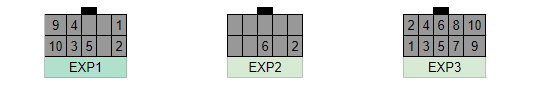
                                The Ender display has 3 connectors EXP 1 to EXP 3. Some of th pins of EXP 1 and EXP 3 are named.

                                EXP 1 from the pcb side:
                                0_1543857341966_b4d8ad8e-c4db-4c3a-816f-52b404f9983c-image.png

                                EXP 3 from the pcb side:
                                0_1543857386030_51e65a80-7f35-4d38-add5-885f73057f5f-image.png

                                Some pins are have the same signals. EXP 2 has no named pins.

                                Maybe it's possible to use 2 standard 10pin cable to connect EXP 1-3 from the Display to Maestro EXP 1 and EXP 2. But until now I didn't have the time to measure and check if it's possible. I'll try to do the next days.

                                1 Reply Last reply Reply Quote 1
                                • Agniusmundefined
                                  Agniusm
                                  last edited by

                                  I can check pinout. I know that exp2 does not work with duets exp2. It probably shorts as leds go out

                                  1 Reply Last reply Reply Quote 0
                                  • arnd13undefined
                                    arnd13
                                    last edited by arnd13

                                    Maybe 2 cables (10 pin). EXP 1 LCD to EXP 1 Maestro and EXP 3 LCD to EXP 2 Maestro.

                                    EXP 1 LCD to EXP 1 Maestro is almost perfect. We only have to check wether Beep and ENC_SW is on EXP 1 LCD.

                                    Agniusmundefined 1 Reply Last reply Reply Quote 0
                                    • Agniusmundefined
                                      Agniusm
                                      last edited by

                                      Here if if i did not missbeeped something
                                      0_1543861344509_ender 3 pins.jpg

                                      1 Reply Last reply Reply Quote 1
                                      • russellundefined
                                        russell @arnd13
                                        last edited by

                                        @arnd13 Hi thank you (i am an absolute beginner as well) this has solved my problem you have got my screen working now i just have to refine it
                                        Thank's again

                                        1 Reply Last reply Reply Quote 0
                                        • Agniusmundefined
                                          Agniusm @arnd13
                                          last edited by Agniusm

                                          @arnd13
                                          Looks like vcc, gnd, buzz and enc_sw will work on exp1, you only need to cut slot in lcd connector and flip ribbon cable?! I will try that.
                                          Another way is just to cut ribbon cable and crimp dupont pins, then use connectors found on pc for power,hdd, reset. They come in multiple sizes and could be salvaged

                                          3dmntbighkerundefined 1 Reply Last reply Reply Quote 0
                                          • Agniusmundefined
                                            Agniusm
                                            last edited by Agniusm

                                            @dc42 @arnd13 I can confirm that display works on EXP1. You need to cut a slot to opposite side of the LCD EXP1 and insert the ribbon cable "the wrong way". Further more if you cut slot on EXP2 on LCD and insert ribbon cable "the wrong way" and connect it to DUET Maestro EXP2, you will have fully functional LCD.
                                            Only encoder will be reversed.
                                            Wow, the trouble i went through crimping those cables when i only needed to cut out 2 slots...

                                            P.S. Probably i was too quick with the post. Weird, but when duet is powered through USB, everything works but when through power terminals the display is blank.
                                            Never mind, had it disabled in config.
                                            So you dont have to enable it in config if its powered by USB but you do when it is power through power terminals

                                            1 Reply Last reply Reply Quote 1
                                            • First post
                                              Last post
                                            Unless otherwise noted, all forum content is licensed under CC-BY-SA