Error: short-to-ground
-
additional: before the error message "short-to-ground" appears, the motor moves a very small distance and that's relatively loud
-
I measure 5MOhm for every combination except if I remove the jumper then I measure as follows (only for the Z-contacts): 5MOhm between 1B+2A on ZA and 5MOhm between 2B and 1A on ZB and the rest is infinite.
-
Do you really mean 5Mohm? That doesn't make sense, unless you have something (e.g. TL smoothers) connected between the Duet and the motors.
-
Tomorrow I'll repeat the measurement and send you a picture.
-
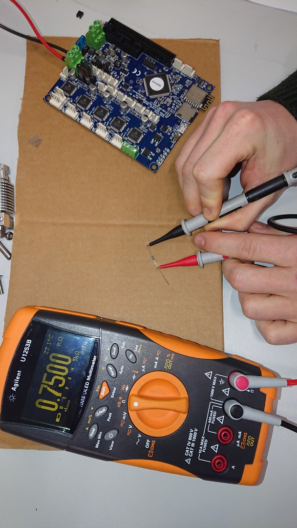
First I checked the multimeter with a 750Ohm resistance and it works correctly. Then I repeated the measurements and measured 5MOhm again. The board was switched off. I think that was the mistake with the last measurement?
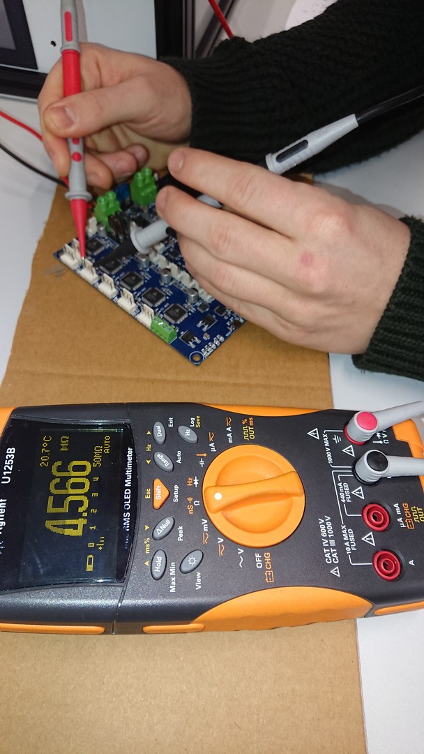
With the board switched on (only 24V) I measure everywhere infinity and between 2B(ZA)/2A(ZB) and 1A(ZA)/1B(ZB) no resistance (exactly -0.03Ohm).
-
@erlerprint3d said in Error: short-to-ground:
First I checked the multimeter with a 750Ohm resistance and it works correctly. Then I repeated the measurements and measured 5MOhm again. The board was switched off. I think that was the mistake with the last measurement?
With the board switched on (only 24V) I measure everywhere infinity and between 2B(ZA)/2A(ZB) and 1A(ZA)/1B(ZB) no resistance (exactly -0.03Ohm).
I'm 99 percent sure he wants you to measure the motor resistance per phase and then measure the resistance between phases to ensure there isn't a short. Take the motor and measure the resistance betweed red and blue, then green and black, and finally between red and black. Do this at the connector that plugs into the duet.
-
Okay, then I misunderstood that. However, I just don't understand why the motors work fine when I use both z-contacts.
Here are the new measurements:
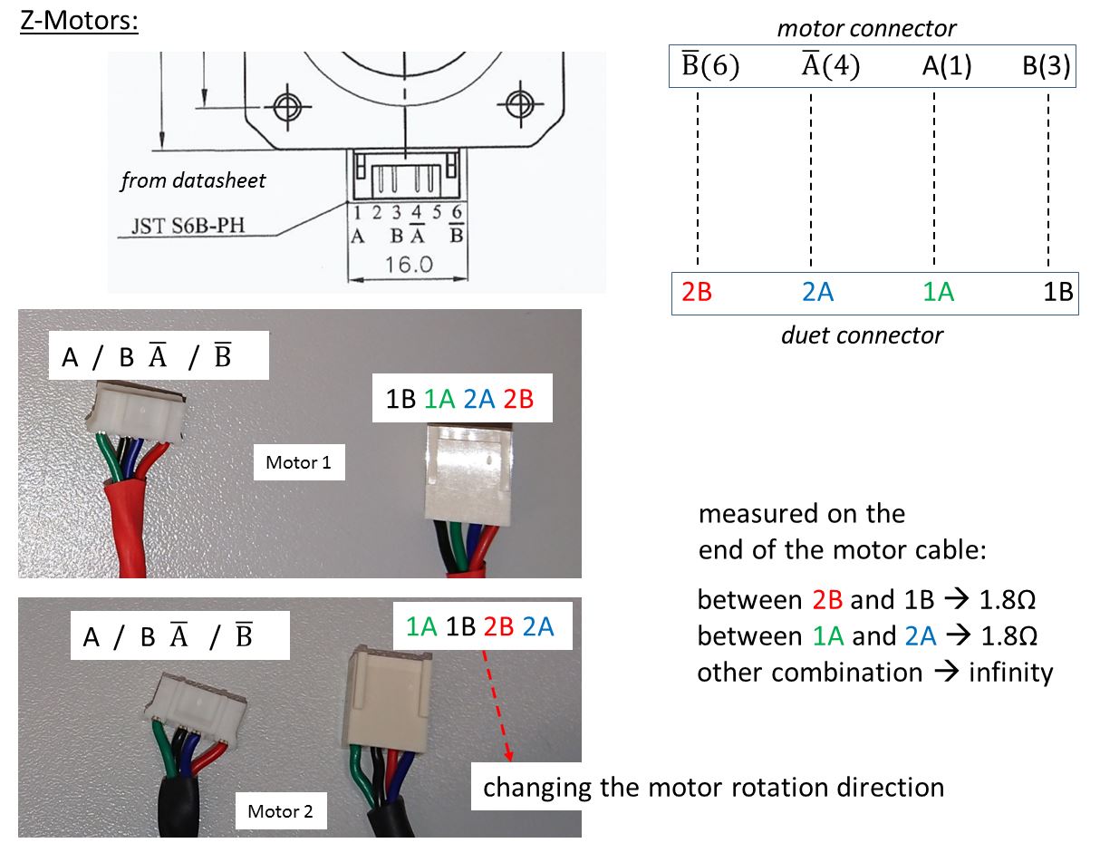
- both Z-Motors (MT-1702E133G6-365E) --> between red and black or blue and green 2.1Ohm; other combination "infinity"
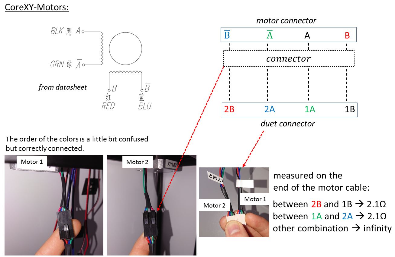
- both CoreXY-Motors (42BYGHM809) --> between red and black or blue and green 1.8Ohm; other combination "infinity"
- max. cable length is 600mm
-
so based on you last measurements, the correct wire order for the connector on the board would be Red, Black, Green, Blue.
(Your current order is Red, Blue, Green, Black, as seen in above photo) -
What is your motor current set to? I had this issue when I accidentally set the motor current way to low.
-
@erlerprint3d said in Error: short-to-ground:
Okay, then I misunderstood that. However, I just don't understand why the motors work fine when I use both z-contacts.
Here are the new measurements:
- both Z-Motors (MT-1702E133G6-365E) --> between red and black or blue and green 2.1Ohm; other combination "infinity"
- both CoreXY-Motors (42BYGHM809) --> between red and black or blue and green 1.8Ohm; other combination "infinity"
- max. cable length is 600mm
Are you sure the colors are correct? If they are you need to rewire your connectors.
-
Yes, it looks like your motors have nonstandard wire colours. This can easily happen if the motors have plug-and-socket connectors on them, and the motors and the cables were not made by the same company.
When you have the motors wired correctly, with power off on the Duet and the motor connected to the 4-pin connector on the Duet, you should measure a few ohms resistance between the 2 pins at one end of the connector, also a few homes resistance between the 2 pins at the other end, and infinity (or several megohms) between the other pairs of pins.
When you connected 2 motors to the Za and Zb connectors, I guess the crossed wires in the 2 sets of cables cancelled out, because Za and Zb on the Duet are in series.
Fortunately, the short-to-ground detection in the drivers appears to have kicked in fast enough to avoid damage to the drivers.
-
@dc42 @Surgikill For me the motors are all connected correctly and the resistances are right. To be on the safe side I have illustrated everything in the pictures. Maybe this will help us to avoid misunderstandings. Or I am simply too stupid for that shit.

@BPisLife I had already tested the motors with higher currents (as in the data sheet). Without success.


-
@erlerprint3d said in Error: short-to-ground:
Okay, then I misunderstood that. However, I just don't understand why the motors work fine when I use both z-contacts.
Here are the new measurements:
- both Z-Motors (MT-1702E133G6-365E) --> between red and black or blue and green 2.1Ohm; other combination "infinity"
- both CoreXY-Motors (42BYGHM809) --> between red and black or blue and green 1.8Ohm; other combination "infinity"
- max. cable length is 600mm
Your last pictures contradict what you said earlier, or did you mean between red an blue 2.1 Ohmn and between Black and Green 2.1 Ohm?? Anyway did you verify the coils on the motor itself (without using a cable)?
EDIT I see now you measure between Red and black 2.1Ohm, so you need to put the cables in the order I told you earlier...
-
Ignore the A and B designations. Trinamic name the phases 1 and 2, and the polarities within a phase A and B, and that is how the pins are labeled on the Duet. But the manufacturer of your stepper drivers has named the phases A and B. Your measurements confirm that you have the motors wired to the Duet incorrectly. See my previous post for what resistances you should measure when they are wired correctly.
It's a shame that the manufacturers of stepper drivers and stepper motors can't agree on a universal naming convention for the 4 connections.
-
I'm going crazy
 . Now of course everything becomes clear. I've already wired some motors at work but all manufacturers of stepper drivers have called the phases A and B. And because everything worked fine if I used both Z-contacts I never thought I had wired something wrong. Unfortunately, I can't test it until tomorrow because I'm building my printer at work. I'll let you know if everything worked fine. Until then many thanks for your efforts.
 -
The motors are moving and I'm so happy. Thank you for your help.
Perhaps in your documentation you could give a short explanation of the different manufacturers' labels, so that nobody else makes this mistake.
Bye.