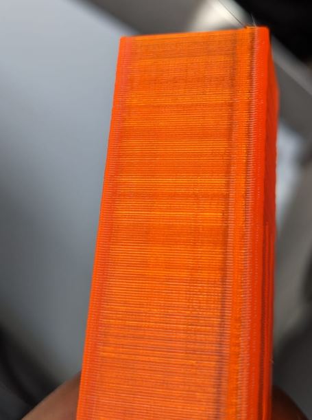
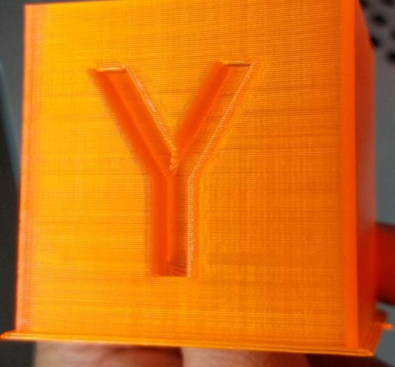
Lines on part every couple of mm
-
So I have been having this problem and I am unable to figure out what is causing it and was hoping someone could help me.
As you can see in the images below every couple of mm there seems to be some lines that appear on the part that is being printed. I am unable to figure out what is causing this (Mostly I think it is a hardware problem but has anyone had a similar issue).
Any help would be appreciated


-
VFA
see
https://github.com/MarlinFirmware/Marlin/issues/13529to fix it use 16 tooth pulleys and 0.9 degree steppers.
-
What type of printer is it, and what are your axis steps/mm and axis motor microstepping?
Is the pitch of the vertical lines exactly 2mm? If yes, do you have any belts that go around non-toothed idlers? If no, what is the exact pitch?
-
@dc42
Its a custom built machine, mostly made using machined aluminium plates and other metal components.- The Z is a 1204 Ballscrew.
- It is hard to measure the lines but I would say they are about 2mm.
- Axis steps/mm is: X80 Y80 Z800 E415 all with 256th Micro-stepping
- Yes the belt does go around non-toothed idlers but only the back of the belt for X and Y axis and for the Z axis the Belt goes around both toothed and non-toothed idlers (back of the belt) and the pitch is 2mm.
-
@rikesh942018 said in Lines on part every couple of mm:
- Axis steps/mm is: X80 Y80 Z800 E415 all with 256th Micro-stepping
Do you really mean that? Those values are fairly typical of something with say 20 tooth pulleys and a Bondtech or Titan extruder using 16X micro-stepping rather than 256 X. Did you mean 16X with interpolation perhaps? Or have you set steps per mm @16X then changed to 256X using M350 afterwards (in which case the firmware will recalculate the steps per mm to something like 1280 for 256X for the X and Y axes).
-
Yep sorry, I mean't 16X with interpolation
-
@rikesh942018 said in Lines on part every couple of mm:
@dc42
Its a custom built machine, mostly made using machined aluminium plates and other metal components.- The Z is a 1204 Ballscrew.
- It is hard to measure the lines but I would say they are about 2mm.
- Axis steps/mm is: X80 Y80 Z800 E415 all with 256th Micro-stepping
- Yes the belt does go around non-toothed idlers but only the back of the belt for X and Y axis and for the Z axis the Belt goes around both toothed and non-toothed idlers (back of the belt) and the pitch is 2mm.
Vertical lines with exactly 2mm spacing, when you are using GT2 belts (2mm pitch) for the X and Y axes, are probably caused by belt teeth. If the lines were caused by inconsistent microstep size then I would expect the pitch to be a binary multiple of 0.2mm instead.
-
Are you talking about horizontal or vertical lines?
-
-
OK, that's called "Z banding". Do a search for that on any of the popular 3D printing forums and you will get lots of hits. The first thing to check is whether the pitch of the banding matches the pitch of your Z leadscrew.
-
but the vertical lines clearly visible on the red cube are VFA
