Modification to Z Offset makes no difference to Z height.
-
I think some of this is just trying to prove that I understand what I put in config and how the printer reacts. I have removed the associated entry in config-override.g as suggested by @deckingman and rebooted the printer. When I home all the printer moves to the front left corner and then drops the extruder down until it touches the bed, at which time it activated the z stop switch (I can watch the Z-stop light come on).
But my config.g currently states that my Z offset should be positive 9.6 (this is not a final setting, it's just to prove the point). But the printer does not stop at 9.6 above the bed. It continues down until it hits the bed again.
So if it's not doing what I have asked it to do in config.g when I am misunderstanding what that entry in config.g is doing.
; Axis Limits
M208 X200 Y200 Z180 S0 ; Set axis maximum
M208 X0 Y0 Z9.60 S1 ; Set axis minimum (should stop at the edge of the bed ready to print position) Currently this just lets paper under the extruder.Another thing with this is that if I alter config.g - for sake of argument to the following;
M208 X0 Y0 Z9.60 S1
But when I "Home All" the extruder moves to the edge of the bed as expected and lowers (in my case until it contacts with the bed). But the web interface shows it's position as Z 9.60 - but it just lowered until it hit the bed, which I would have expected to show a negative number?
-
@b0m0a0k As we've said, don't alter M208 - keep your axis minumum at Z=0.
I don't use a BL touch but I'm assuming it works like any other probe. In which case the best way to home Z, IMO is to do a single probe using G30. You define the offset using G31. So you bring the bed and probe closer together until the probe triggers. Note the Z height. Then you move closer together still until the nozzle is just gripping a very thin piece of paper and note the Z height again. Then you take one Z height away from the other and the difference is the offset. This is the value you put into G31. From there after, whenever you probe the bed using G30, the firmware "knows" that Z=0 (nozzle just touching the bed) is G31 mms away from the point where the probe triggers.
-
Hi. OK, so I reverted All Z references back to "0" and reran the setup sequence as documented in the BeTrue3D tutorial (that's a great document by the way). I ran through to section 3 and again stumbled at lowering the nozzle until it touches the bed. I issued M564 S0 as suggested by @Phaedrux and this allowed me to continue jogging the nozzle down until it touched the bed.
Ran the configuration process three times as suggested by the tutorial and completed the setup successfully.
Ran my first Mesh Grid Compensation sequence and all hell broke loose. It's obvious by just looking at the setup that the probe was going to hang over the edge of the bed and not trigger, so I need to go read up on how you define the Mesh grid pattern. For now the nozzle happily descends until it crashes into the bed and I have to perform an emergency stop


... it's a learning curve
-
@b0m0a0k Don't forget that anything that is in config-override.g will over ride whatever is in config.g. I suggest to delete the override.g file, at least for now. It'll save a bit of confusion because then you'll know that everything is in one place and one place only.
-
@deckingman That's a great suggestion and one I'm happy to follow. I hadn't done it prior to this because that file starts with "This is a system-generated file - do not edit" which I assumed meant that it needs to be there.
Thanks for the clarification.
-
@b0m0a0k said in Modification to Z Offset makes no difference to Z height.:
@deckingman That's a great suggestion and one I'm happy to follow. I hadn't done it prior to this because that file starts with "This is a system-generated file - do not edit" which I assumed meant that it needs to be there.
Thanks for the clarification.
Another possibility is to remove or comment out the M501 line at the end of config.g so that config-override.g is not run. Then anything you save using M500 will still be written to config-override.g but ignored. You can use the editor in DWC to see what has been written to config-override.g and transfer lines from there to config.g if you need to, for example after tuning heaters.
@b0m0a0k said in Modification to Z Offset makes no difference to Z height.:
so I need to go read up on how you define the Mesh grid pattern
The M557 command defines the limits of the mesh grid; but you must also define the Z probe offset from the nozzle in the G31 command.
-
When I set up the Mesh Grid am I right in thinking that I am working out the coordinates where the probe will contact the bed and not where the extruder nozzle will be. If I do the former the probe won't always trigger because it will go off the edge of the bed?
This does of course mean that my bed leveling probe area is greatly reduced due to the distance between the nozzle and the probe - caused by the mounting location of the probe?

-
@b0m0a0k said in Modification to Z Offset makes no difference to Z height.:
"This is a system-generated file - do not edit" which I assumed meant that it needs to be there.
Possibly it was generated by saving the results of a heater PID tuning with M500?
-
@b0m0a0k said in Modification to Z Offset makes no difference to Z height.:
This does of course mean that my bed leveling probe area is greatly reduced due to the distance between the nozzle and the probe - caused by the mounting location of the probe?
Yes, this is common with probes that are offset from the nozzle, there will likely be some areas of the bed that the probe cannot reach, and areas where it will overhang the edge of the bed. The firmware does attempt to do some extrapolation for the areas that it cannot reach, so if it's generally flat to begin with, it's not likely to be much of an issue.
I find the best way to work out the extents of the mesh grid is to take the axis limits and your probe offset and the difference between them becomes your grid area.
For example, if your X axis is 200mm long from 0 to 200, and your probe is offset from the nozzle by +20mm that means your grid would begin at X20 and end at 200. Likewise, if your Y axis is 200mm long from 0 to 200, and your probe is offset by -20mm (ie, in front of the nozzle) then your Y grid would begin at Y0 and end at Y180. This assumes that the nozzle cannot travel off the edge of the bed at all. If it can travel farther than the edge of the bed, then your probe may be able to reach more.
-
Thanks for the confirmation @Phaedrux that all makes sense. I have calculated my Mesh by moving the extruder to all 4 corners and making a note of the coordinates. Then I have rerun this to allow for the probe overhand at the front of the bed and noted these adjusted settings.
I have ended up with this;
M557 X28:190 Y49:185 S20 : PROBE on the edges setting
I am now generally finding reasons not to click on Run Mesh Grid Compensation just in case I have programmed the printer for insanity by mistake

-
Well, Holy Hannah, that didn't blow up!

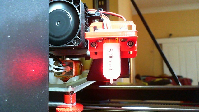
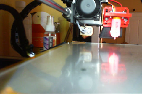
This is my 1st attempt, the test stopped short of where I though it would at the back of the bed - you can see it's well short of the edge.

I guess some fine tuning is in order. Sorry about the fuzzy nature of the second photo, my webcam did not want to prioritize focus on the far object.
-
@b0m0a0k said in Modification to Z Offset makes no difference to Z height.:
When I set up the Mesh Grid am I right in thinking that I am working out the coordinates where the probe will contact the bed and not where the extruder nozzle will be.
Yes, where the probe will contact the bed - assuming you have set the correct probe X and Y offsets in G31. The firmware will take those into account when calculating where to place the nozzle for each probe point. If that position is outside the limits that you declared using M208, that point won't be probed.