CONN_LCD wiring for external driver
-
Its locked from the beginning and remain locked till switch off, I've tried increasing the T2.5 to till T5, but no change , the stepper getting lil warmer , other than that no change happening, pls help
-
My guess is that the Enable input of your driver is actually a Disable input, and that the CONN_LCD outputs don't provide sufficient drive to your stepper drivers.
-
In that case, what could be the solution - Can I remap E0 to U and CONN_LCD pins to E0 (so that I can have Nema17 connected to CONN_LCD for extruder 0 - will this work -or please suggest the alternative to run this system
-
See https://forum.duet3d.com/topic/9683/additional-stepper-drivers-on-duex-5 for a suggested buffer circuit between CONN_LCD and external drivers.
-
dc42 ADMINISTRATORS 6 Apr 2019, 15:01
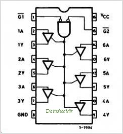
For a 74HCT365 or 74HCT367 (either will do) in 16-pin DIL package:
Pins 1,8,15 - ground
Pin 16 - +5V
Pins 2,4,6,10,12,14 - inputs from CONN_LCD
Pins 3,5,7,9,11,13 - +outputs to stepper driver +input pins (connect the -input pins of the stepper driver to ground)Also connect a 0.1uf capacitor between pin 16 and ground.
A few stepper drivers have a common +input pin. For those, use a 74HCT366 or 74HCT368 instead, connect the driver -input pins to the outputs of the chip (pins 3,5 etc.), and connect the common +input of the driver to +5V.
Take great care not to short +5V to any of the other pins on CONN_LCD.
HTH David
I've done the level shifting circuit, one clarification required,
Pins 2,4,6,10,12,14 - inputs from CONN_LCD
Pins 3,5,7,9,11,13 - +outputs to stepper driver +input pins (connect the -input pins of the stepper driver to ground)
Which means, should I connect 2,4,6 to Driver Pulse+, DIR+, ENA+
10, 12, 14 to Pulse-, DIR-, ENA- respectively? -
Here is a pinout diagram of the 74HCT365:

Connect /G1, /G2 and GND to ground, and connect Vcc to +5V. For the rest, pins 2 and 3 are one input/output pair, 4 and 5 are another, and so on. So here is one possible connection scheme, for one external driver:
STEP_10 from CONN_LCD to pin 2 (1A)
DIR_10 from CONN_LCD to pin 4 (2A)
EN_10 from CONN_LCD to pin 6 (3A)Pin 3 (1Y) to STEP+ on external driver
Pin 5 (2Y) to DIR+ on external driver
Pin 7 (3Y) to ENA+ on external driver
STEP-, DIR- and ENA- from external driver to GND.You can use the A and Y pins on the other side of the chip in a similar way for a 2nd external driver.
-
Thank You so much David, I wonder how could you mange to provide solution for every problem worldwide... Thank you once again , I'll connect as instructed..
-
Thank you so much, Its working flawlessly ...help me with endstop connectivity for this channel 10
-
@milan said in CONN_LCD wiring for external driver:
Thank you so much, Its working flawlessly ...help me with endstop connectivity for this channel 10
What endstop connectivity problem do you have?
-
Should we use Stop 10 Enc_B and Gnd for channel 10 Endstop?
Do we need to remap the other endstops in firmware as we do for Axis remap, we are using channel 5,6&7 for XYZ. Thanks
-
In firmware 2.03 and earlier, when you create axes the endstop inputs are allocated automatically. So if you create axes U and V in your M584 command then U will use the E0 input and V will use the E1 input.
In firmware 3.0 beta you have to allocate endstops for additional axes and specify the input pins using M574.