Five bar parallel Scara
-
I love strange kinematics, and when I discovered the parallel scara I had to build one.

The Duet did not have support for this kinematics in stock firmware but @JoergS5 had an almost complete implementation that we have developed further. The firmware works very good now.
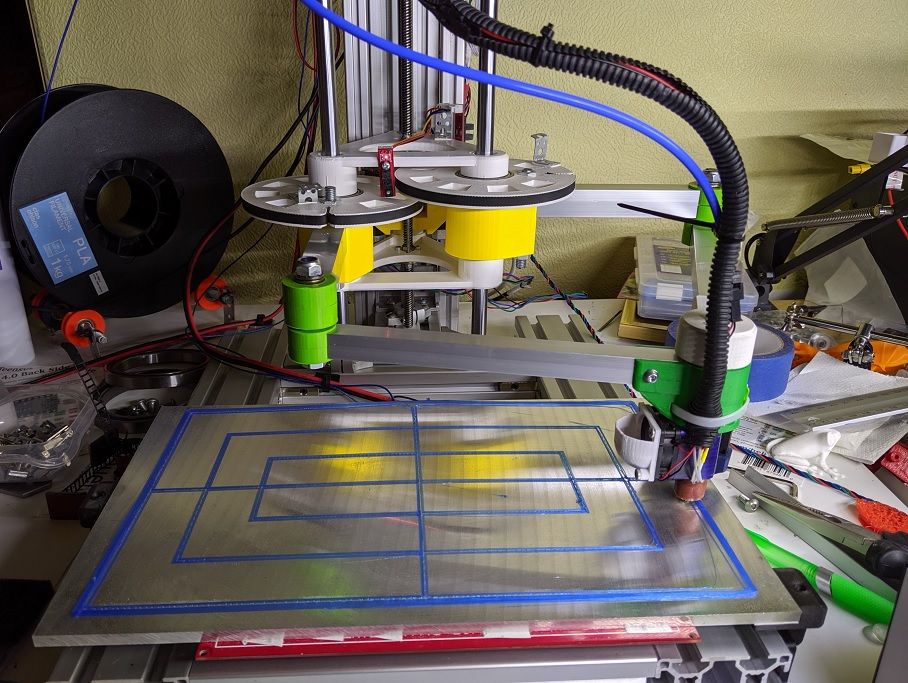
The machine is made mostly of printed parts and items you can easily get hold of, and a hacksaw and hand drill. No machined parts. The precision is not the best but it still works pretty good (just a nightmare to calibrate). It's still a prototype/proof of concept so it does not look very good and many parts are stuff I had laying around.
The body rides on 3 12mm rods with LML12UU-like bearings, and has one leadscrew. The inner joints have two 6806 bearings per arm. The elbows use two 8mm thrust bearings each, preloaded with an m8 rod, a crude solution that works very well. That joint is very stiff. The hotend joint has two 6704 (20x27x4) very thin and light bearings inside. Lots of bearings.
The motors driving the arms are 48mm 0.9degree NEMA 17 with a 20t pulley leading to a 200t printed pulley. This gives a gearing of 1:10 which is very much on the low side. 1:30 would be far better. But upping the microstepping to 64 or even 256 saves the situation. A problem with 256 microstepping is that the Maestro starts to get stepping rate problem over 400mm/s.
Using a normal gearbox is not possible due to their backlash. A machine like this needs a gearbox with almost no play, like a harmonic drive. A belt gearbox works pretty good but the gearing is limited due to size.With the 180 and 216 mm long arms the printing area is approximately 300x200mm. The actual print area is actually half-circleish shaped and quite a lot bigger.
The printer can move at blazing speeds and accelerations without any drama and shaking. The kinematics is similar to a polar delta but just 2 axis instead of 3. Currently it has a fair amount of ghosting at high speed/acceleration, but prints very good at a more reasonable 60mm/s and 2000 acceleration. I think the ghosting is due to a far too wobbly tower, or possibly flex in the belts. I have got some metal clamps for the 12mm rods and some more 3060 extrusion in the mail, it might help.
I made a little video showing it moving fast https://www.youtube.com/watch?v=MW8HApFoy38.
Here is an earlier version doing the first reasonably successful benchy print.

Those arms were made of small U-beam and far too wobbly, changing to bigger 20 mm square beams made a massive difference.The very first little prototype to get a feel for the kinematics, a very useful little toy
")

-
Good to see you've got this working well! Is one of you going to send me a PR to add this kinematics to the standard firmware?
Duet WiFi hardware designer and firmware engineer
Please do not ask me for Duet support via PM or email, use the forum
http://www.escher3d.com, https://miscsolutions.wordpress.com -
-
@joergs5, please do. We need a joint repo to work from, we should set up a common fork after that. I poke around in the code at times, it's not complete, yet.
I did a push today of my local changes to my repo at https://github.com/bondus/5barscara/tree/master/rrf. Mostly cosmetic changes, but something important might be hiding in there. If we had a joint repo I will behave, commit more often and add proper comments -
@bondus I will test your code corrections with my printer at the weekend and will make the PR then (maybe I should do it for RRF3 only, what do you mean? *)). I will add some unit testing of the most imporant methods. I have gathered some ideas to avoid backlash, so no need to correct the firmware in this regard as I planned to do.
*) if we work and test with only one version of RRF, effort to develop further will be lower, deployment easer, and RRF3 is the future anyway. If someone wants to use it in 2.03, it's easy to downport.
-
The fancy new rod holders made no difference for the ripples. They made the tower quite a lot stiffer and they look good

The ripples are pretty high frequency and keeps going for a long while, not much dampening.
This print is in shiny black to show all flaws and held at a very specific angle to see the ripples, prints generally look good.

-
@dc42 @bondus I made a PR #297 now into v2-dev. The files compile ok, the PR should only contain the two files .h and .cpp of the kinematic. Please include into your main RRF. I am sure there are bugs or improvements left, so there will be updates.
bondus, I changed a few of the methods to be the same signature as the original methods, because they were overridden methods. I hope I didn't break your code. (I saw now that the changed methods are due to changes between v2 and v3)
-
@joergs5, Sweet!
After some battling with the RRF build (the build environment is quite fragile) I got it building and running. It works perfectly fine.
I never managed to get v3 running properly. After some workarounds with the homing issues I got it moving. But it refused to print any gcode files, it did nothing after starting a gcode file. -
@bondus I will try RRF3 after finishing my printer build. First priority is to build the optical encoders for the endstops with ESP32-CAM (I will use the mechanism for Z axis also), then as stiff arms as possible. I will try dry plain bearings with plastic surfaces at the sliding surface. PTFE (teflon) has lowest friction, nylon a bit worse (but easier to 3D print).
-
@JoergS5 slightly offtopic, but: would the optical encoder based endstop also work on a traditional SCARA arm?
-
@oliof yes, it will work with all actuators which rotate. The advantage is that the endstop can be approached from both sides and can tell the absolute angle at any time. I will write a documentation for diy steps and software.
-
@joergs5 said in Five bar parallel Scara:
@dc42 @bondus I made a PR #297 now into v2-dev. The files compile ok, the PR should only contain the two files .h and .cpp of the kinematic. Please include into your main RRF. I am sure there are bugs or improvements left, so there will be updates.
v2-dev is no longer used, it was for the initial development of RRF 2.0. The branch used for firmware 2.x is now the dev branch. So that is there your PR should be targeted.
Duet WiFi hardware designer and firmware engineer
Please do not ask me for Duet support via PM or email, use the forum
http://www.escher3d.com, https://miscsolutions.wordpress.com -
@dc42 I am confused now. Which branch shall I use for the PR. Or other proposal: I implement it for RRF 3 dev branch and withdraw the PR 297. When you finished your Duet 3, I will be ready for the RRF3 PR.
-
@joergs5, yes a PR for RRF3 on the v3-dev branch would be good, if you have tested it.
-
@dc42 I will change to RRF3 and correct the bug we found. Good luck with your Duet 3, I am very curious what it will be like!
-
-
@bondus That's good news if you can test RRF3.
I am used to use Eclipse for Java, but I am often confused by the eclipse behaviour. Especially at RRF I am confused by the different setting for the different hardware and the error message that pop up here and there for some .h files not being compilable. I understand why David has it in the code, but my Eclipse tells me about errors, because a grayed file cannot be compiled or found.
I thought about a fork and throw out all those RADDS, Duet 085 and other hardware which is not relevant for my hardware. And I would like to throw out Delta, heatbed calibration code to have the pure logic in the code which I need, and to understand the code. But it's a lot of work, and then I have to synchronize somehow.
-
I woke up my old printer and gave it a new fancy 300x200mm machined bed.
Only to realize why I have not used it very much. Straight lines are not always straight when printed. It is not made with the precision needed for an arm like this.

I need to properly measure all the arm lengths and homing angles and put them into the firmware and all should be fine. -
Nice build, @bondus. I thought about calibration for my printer also. Ich will go the other way: meassure the results for a given configuration and then calculate back what the dimensions of the arms are.
E.g. move to 0,0 and 300,300 with Gcode and then check what abbreviations of the expected positions are. Calculate back the true arm lengths and actuator angles. I hope this will give some corrections of other errors also (hinge movements, arm bending e.g.) -
@JoergS5 said in Five bar parallel Scara:
meassure the results for a given configuration and then calculate back what the dimensions of the arms are.
I tried an approach like that a while back but never got it working, it should work in theory, so it was my execution that was wrong.
There are 7 unknowns that might need adjusting: The length of each of the five "bars" and the two homing angles. You will need quite a few measurements to get a single solution to the adjustment equation.
Now with a bigger, and very flat, bed I also noticed that the head does not move in a perfect plane, it's about 0.3mm higher at the left and right edges compared to the middle. The quick and dirty solution is to add a bed probe, or I could start looking for non-perpendicular angles on the machine.