Five bar parallel Scara
-
@joergs5, yes a PR for RRF3 on the v3-dev branch would be good, if you have tested it.
-
@dc42 I will change to RRF3 and correct the bug we found. Good luck with your Duet 3, I am very curious what it will be like!
-
-
@bondus That's good news if you can test RRF3.
I am used to use Eclipse for Java, but I am often confused by the eclipse behaviour. Especially at RRF I am confused by the different setting for the different hardware and the error message that pop up here and there for some .h files not being compilable. I understand why David has it in the code, but my Eclipse tells me about errors, because a grayed file cannot be compiled or found.
I thought about a fork and throw out all those RADDS, Duet 085 and other hardware which is not relevant for my hardware. And I would like to throw out Delta, heatbed calibration code to have the pure logic in the code which I need, and to understand the code. But it's a lot of work, and then I have to synchronize somehow.
-
I woke up my old printer and gave it a new fancy 300x200mm machined bed.
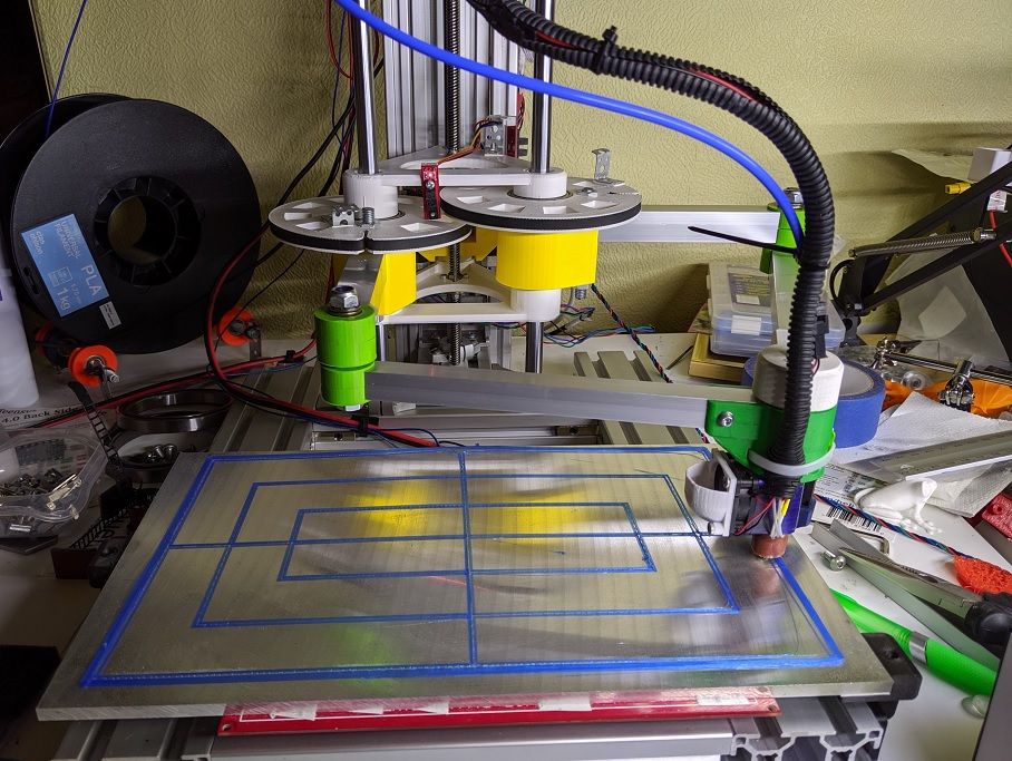
Only to realize why I have not used it very much. Straight lines are not always straight when printed. It is not made with the precision needed for an arm like this.

I need to properly measure all the arm lengths and homing angles and put them into the firmware and all should be fine. -
Nice build, @bondus. I thought about calibration for my printer also. Ich will go the other way: meassure the results for a given configuration and then calculate back what the dimensions of the arms are.
E.g. move to 0,0 and 300,300 with Gcode and then check what abbreviations of the expected positions are. Calculate back the true arm lengths and actuator angles. I hope this will give some corrections of other errors also (hinge movements, arm bending e.g.) -
@JoergS5 said in Five bar parallel Scara:
meassure the results for a given configuration and then calculate back what the dimensions of the arms are.
I tried an approach like that a while back but never got it working, it should work in theory, so it was my execution that was wrong.
There are 7 unknowns that might need adjusting: The length of each of the five "bars" and the two homing angles. You will need quite a few measurements to get a single solution to the adjustment equation.
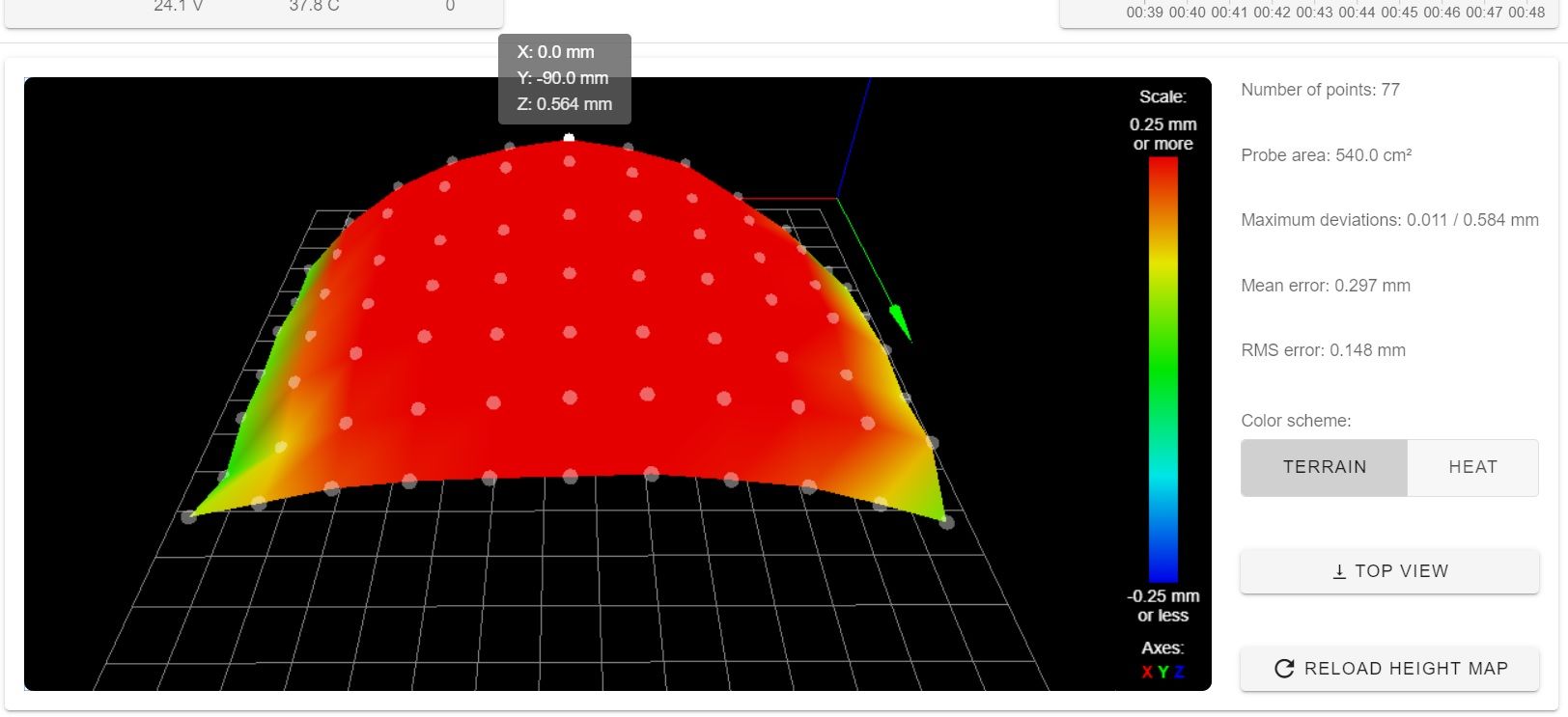
Now with a bigger, and very flat, bed I also noticed that the head does not move in a perfect plane, it's about 0.3mm higher at the left and right edges compared to the middle. The quick and dirty solution is to add a bed probe, or I could start looking for non-perpendicular angles on the machine.
-
@bondus My ideas for better Z accuracy are (sorted by cost, cheapest and easiest first):
- counterweights at the other side of all hinges at the opposite side of the arms (leverage law or ball bearings could produce your 0.3 mm differences)
- hinges supported with two arms each vertically, so the hinges are more precise
- hinges with metal material
-
@JoergS5, I really think that some critical parts of the arm should be machined. Tiny errors in precision in the parts holding the proximal arms are amplified further out. Possibly you could make some clever parts where you could tune it by tightening/loosening different bolts. This is not unique for this kind of robot arm, any arm moving by rotating a join will have the errors amplified. Linear rails are far easier to use.
My design with the whole arm assembly moving up and down on the z-axis is tricky to design. There is very little room to place screws from the lower part to the upper part, to preload the bearings. The large pulleys and the goal to keep the arms rotation range as big as possible does not make it easy. The current version is far from ideal.
I am working on a better version, but every time I start fusion I lose a day. It's very mesmerizing to 3D CAD.
I installed an old precision piezo to measure the Z error properly. I had one of the the old crummy versions with a drilled piezo element laying around. It still works fine.
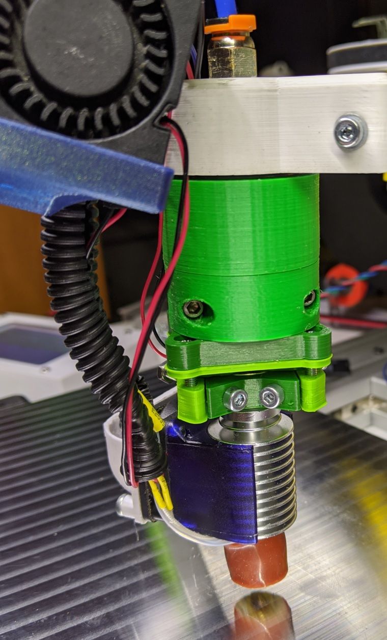
I can see that the arms lifts the actuator the further out the actuator is. It's not due the tower being at the wrong angle, or the weight of the arms bending it down. Some other angle(s) are wrong. It's a complicated machine
")
It's officially spring here now, at least on my balcony. The bulbs from last year are flowering.


-
@bondus Holy crap, is that a flower? It's the dead of winter here. I feel like I haven't seen colours like that in ages.
-
@bondus Nice narcissus, it becomes spring!
I was thinking a lot about precision of parallel scara the last months, especially of the hinges. Additional ideas to my last ideas are:
- supporting the arms by steel wires like at some cranes like in
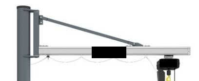 This goes into the direction of tensegrity also.
 - from compliant mechanism replacing ball bearings with something like in https://3dprint.com/252086/developing-3d-printed-soft-actuators-for-robotic-arms/ (I mean the black one, called revolute joint in the image) or https://www.youtube.com/watch?v=0MQXoVKrRbo One can get about 30 degree with the first one, called butterfly hinge also. Other ideas are Hylite hinge and crossed springs (german: Kreuzfedergelenk), but one gets only about 15 to 30 degree rotation. Hylite is very interesting, because the multimaterial polypropylene with something carbon based could be printed easily with the new multimaterial printers.
- trying calibrate the actuators separately by rotating them the three directions each, so hinge errors are minimized. But I didn't calculate how to do it best.
I final idea: we had some interesting discussion about uneven printing, so a fast z movement would be interesting. This movement can be small (layer height * small number), so some piezo actuator which moves the hotend could be used. This piezo mover could correct your arm height errors also. The supplier https://www.cedrat-technologies.com/en/technologies/actuators/piezo-actuators-and-electronics.html show what is possible with stacked piezo elements.
- supporting the arms by steel wires like at some cranes like in
-
It's fun to see Fusion 360 struggle with the five bar kinematics. It's doing a surprisingly good job.
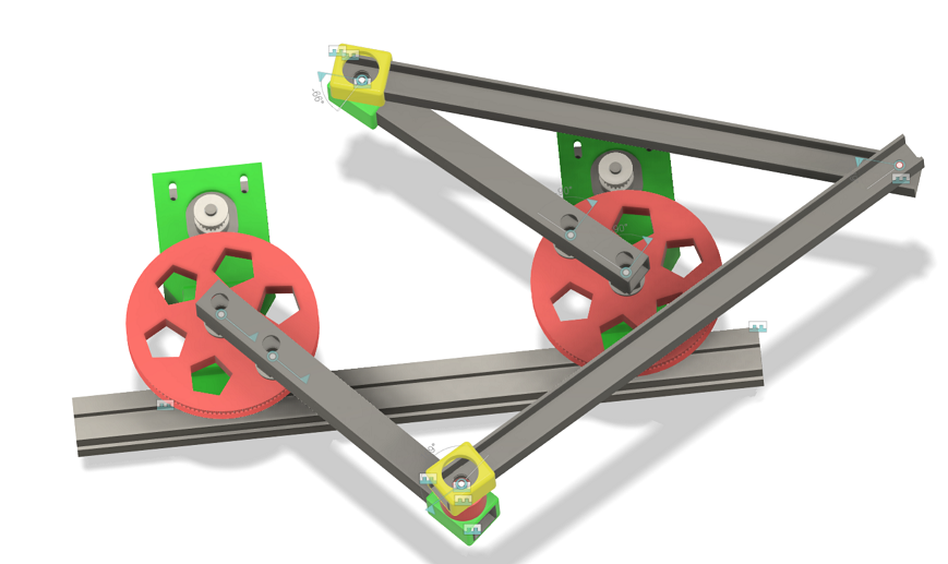
I'm working on a smaller version with greater movement range that will eventually evolve into a version 2 of the printer. The current version has many flaws.
I wish I had a lathe and a router to make some small items. There are some critical parts in the joints that would benefit greatly from being made in steel or aluminium. Perhaps there is a makerspace nearby...
-
@bondus this is the direction I go also. My construction has a larger big wheel (your red ones), so the gear between stepper and wheel is about 1:30 (results stepper 10 turns/s => arm hotend speed about 10/30*300 = 100 mm/s). The hinges are critical imho, so I support the axis with two ball bearings each. I have not decided yet wheter I will use two arms each or using wires to stabilize. Instead of steel arms you could use carbon fiber also: similar e-module, lighter and less thermal expansion, but more expensive and more difficult to glue/connect.
-
@JoergS5 This version has two ball bearings too, behind the pulley. I preload the poor deep groove bearings by tightening a lock nut a little bit. They are really not made for that kind of axial load, but it works. I have some angular bearings that I might use further on, but I save them for now. They are prone to fall apart and were pretty expensive.
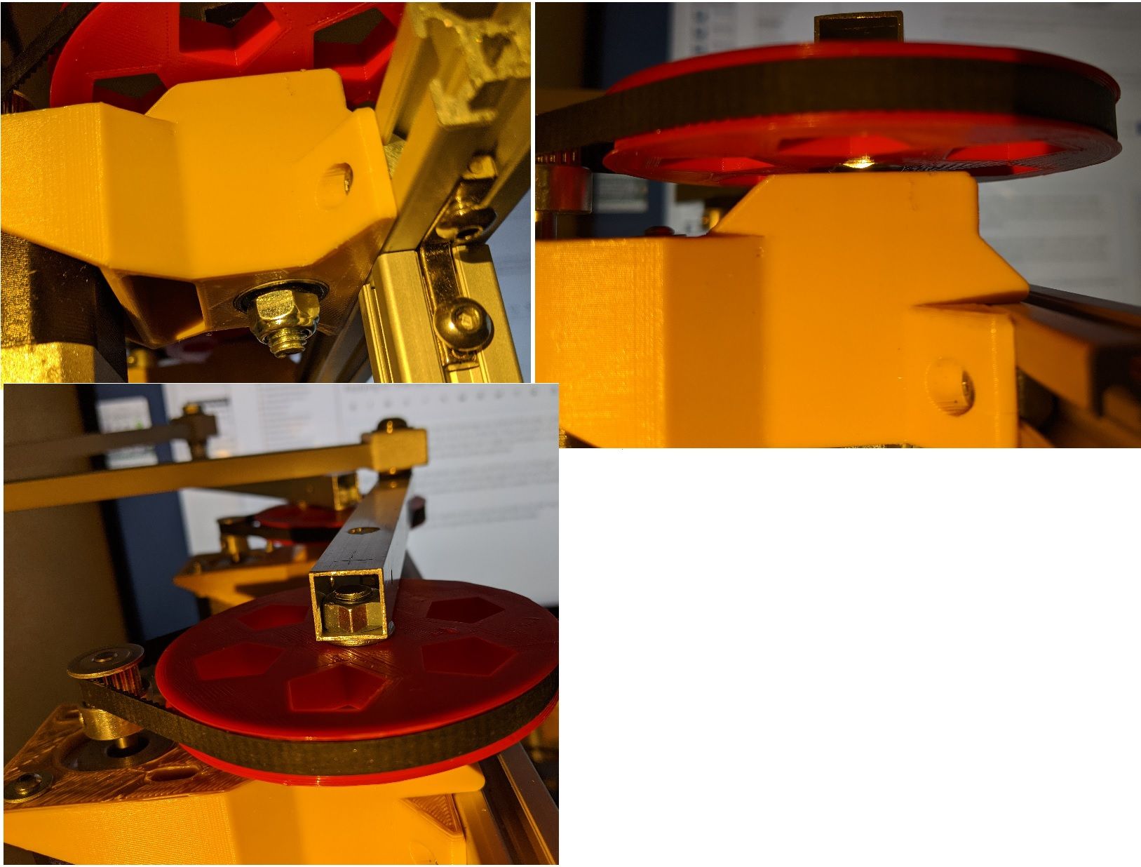
A very simple construction. Two plastic parts, two bearings and three nuts.One idea to avoid the soft plastic could be use let the axle run through a drilled hole in a 3060 extrusion or other metal part, push the bearings against that and then push the arm directly onto the bearings. Some washers and spacers will be needed. The printed plastic parts would just hold things in place.
The thin walled aluminium square arms I use are actually very stiff. The U-beams in the drawing are just for testing, they are not good at all, they twist very easily.
-
Only 0.15mm deflection when adding 180g to the actuator. (That big bearing weighs 180g). Not bad.
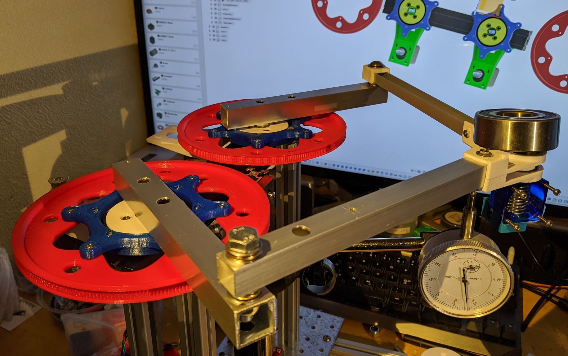
I went for a bigger bearing at the shoulder, a 6810 at the top and a small ID 8mm below the 2040 extrusion. It made a massive difference with a big diameter bearing.
The weak point now is definitely the elbows.
-
@bondus I like how you constructed the "big wheels", which makes 3D printing easier, printing multiple parts. May I copy this idea?
")
-
@JoergS5 I split them because it takes very long to print the pulleys, they have to be printed fairly slow to get decent teeth. And it makes easier to swap pulley size or quickly modify the inner part. Copy all you want, perhaps you can design better looking spokes.
-
Just missing two endstops and an extruder and it's ready to go.
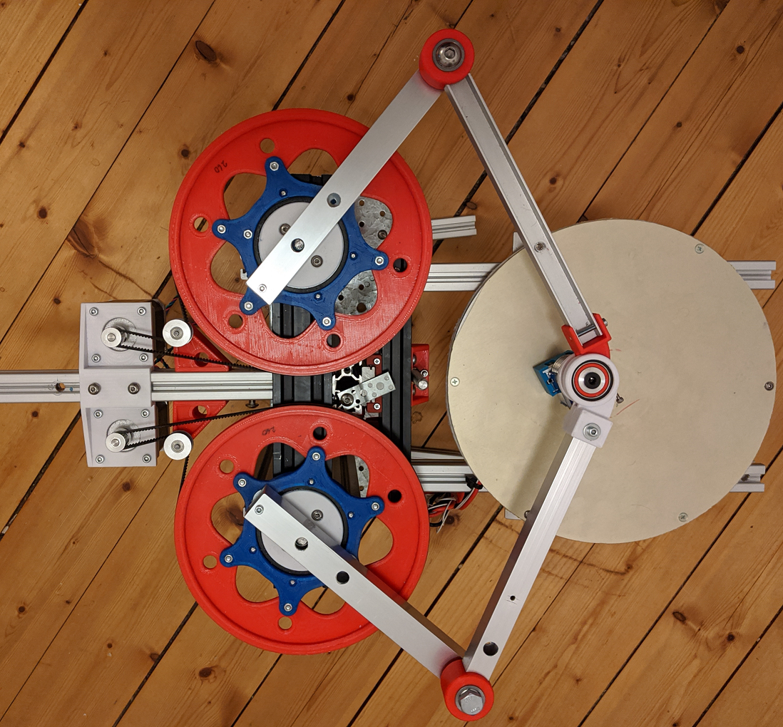
I spent hours calibrating it yesterday. Since nothing is really adjustable that meant filing on plastic pieces and very slightly bending and twisting the arms.
It is critical that all joint bearings work in the same plane, it is an overconstrained system in the z-plane. If not all 5 joints are in the same plane they will fight each other and create a strange z-deviation map.
Any errors can easily be seen by keeping the actuator at the same spot but changing the arms to different work modes.I'll put adjustable endstops at right angles, 0deg for right arm and 180deg for left arm. That way they are easy to calibrate.
Possibly they are better placed straight back if I will use work mode 1 or 4. It can be a bit tricky to home the machine from an unknown position. -
After some quick tuning of the hotend and more mechanical calibrations I managed to print this stunning benchy, at 120mm/s and 2500mm/s^2 acceleration. I'm surprised!

-
Some videos of the beast in action:
Printing of a calibration item at 120mm/s.
https://youtu.be/yubS3_OUhQsSame thing but in a different work mode (arms at a different angle). I have tried to make this machine as flexible as possible to be able to test all cases of the firmware. If I extend the outer arms a little bit the inner arm can travel all the way around to the backside. Right now the hotend collides with the pulleys.
https://youtu.be/1IpzSe83RkQ