Bed Composition does not seem right
-
Hello I am having some issues with bed composition and I am not sure what to do to correct.
After completed manual bed leveling assistant and bed composition performed by G32 with glass bed at temperature I get the following height map.
 (origin of bed is left, front)
Looks pretty good. But when I begin a print I get the following
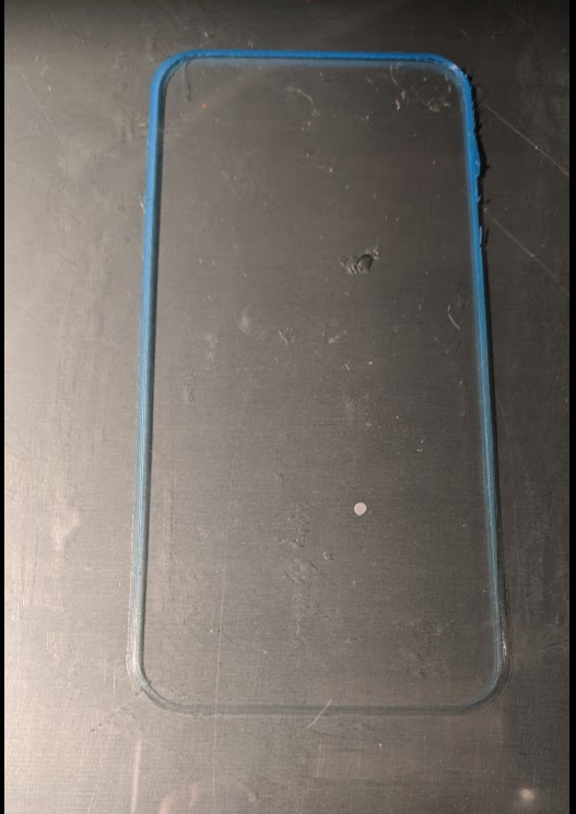 (origin of bed is left, front)
Why is the bottom of the print smooshed more than the top? Is autoleveling not keeping the nozzle the same distance? What step am I missing?
config file
; Configuration file for Duet WiFi (firmware version 1.21)
; executed by the firmware on start-up
;
; generated by RepRapFirmware Configuration Tool v2 on Sun Mar 17 2019 11:31:51 GMT-0400 (Eastern Daylight Time); General preferences
G90 ; Send absolute coordinates...
M83 ; ...but relative extruder moves
M575 P1 B38400 S1 ; Baudrate for Paneldue 38400
M667 S1 ; Select CoreXY mode; Network
M550 P"My Printer" ; Set machine name
M552 S1 ; Enable networkM586 P0 S1 ; Enable HTTP
M586 P1 S0 ; Disable FTP
M586 P2 S0 ; Disable Telnet; Drives
M569 P0 S0 ; Drive 0 goes backwards
M569 P1 S0 ; Drive 1 goes backwards
M569 P2 S1 ; Drive 2 goes forwards
M569 P3 S1 ; Drive 3 goes forwards
M350 X16 Y16 Z16 E16 I1 ; Configure microstepping with interpolation
M92 X80 Y80 Z412 E97 ; Set steps per mm
M566 X600.00 Y600.00 Z100.00 E120.00 ; Set maximum instantaneous speed changes (mm/min)
M203 X6000.00 Y6000.00 Z180.00 E1200.00 ; Set maximum speeds (mm/min)
M201 X3000.00 Y3000.00 Z100.00 E250.00 ; Set accelerations (mm/s^2)
M906 X1300.00 Y1300.00 Z1300.00 E1000.00 I30 ; Set motor currents (mA) and motor idle factor in per cent
M84 S30 ; Set idle timeout; Axis Limits
M208 X-3.6 Y-18 Z0 S1 ; Set axis minima
M208 X330 Y330 Z400 S0 ; Set axis maxima; Endstops
M574 X1 Y1 S0 ; Set active low and disabled endstops; Z-Probe
M574 Z1 S2 ; Set endstops controlled by probe
M307 H7 A-1 C-1 D-1 ; Disable heater on PWM channel for BLTouch
M558 P9 H10 F100 R0.2 T2000 A5 B1 ; Set Z probe type to bltouch and the dive height + speeds
G31 X-10.7 Y59.1 Z3.9 P25 ; Set Z probe trigger value, offset and trigger height
M557 X50:270 Y50:270 S20 ; Define Mesh grid, probe from X=50 to 270, Y=50 to 270mm with a mesh spacing of 20mm; Manual Bed Leveling Assistant
M671 X80:80:280:280 Y80:262:262:80 P0.5 ; adjusting screws at front left (16,-18), rear left (16,262) rear right (330,262) front right (330,-18); Heaters
M305 P0 T100000 B4138 R4700 ; Set thermistor + ADC parameters for heater 0
M143 H0 S120 ; Set temperature limit for heater 0 to 120C
M305 P1 T100000 B4138 R4700 ; Set thermistor + ADC parameters for heater 1
M143 H1 S280 ; Set temperature limit for heater 1 to 280C
M307 H1 A325.0, C62.7, D3.5 S.6 B0 ; Heater 1 model: gain 349.1, time constant 67.3, dead time 3.5, max PWM .6, mode: PID
M570 H1 P10 T15 S15 ; Configure heater fault detection (H# heater number, P time in seconds for anomaly to persist, T temp
excursion setpoint, S time in mins before print canceleld); Fans
M106 P0 S0.3 I0 F500 H-1 ; Set fan 0 value, PWM signal inversion and frequency. Thermostatic control is turned off
M106 P1 S1 I0 F500 H1 T45 ; Set fan 1 value, PWM signal inversion and frequency. Thermostatic control is turned on; Tools
M563 P0 D0 H1 ; Define tool 0
G10 P0 X0 Y0 Z0 ; Set tool 0 axis offsets
G10 P0 R0 S0 ; Set initial tool 0 active and standby temperatures to 0C; Automatic power saving
M911 S21 R23 P"M913 X0 Y0 G91 M83 G1 Z3 E-5 F1000" ; Set voltage thresholds and actions to run on power loss; Custom settings are not configured
; Miscellaneous
M501 ; Load saved parameters from non-volatile memorybed file
; bed.g
; called to perform automatic bed compensation via G32
;
; generated by RepRapFirmware Configuration Tool v2 on Sun Mar 17 2019 11:31:50 GMT-0400 (Eastern Daylight Time)
G90 ; absolute positioning
M561 ; clear any bed transform
M401 ; deploy mechanical Z probe
G30 P0 X80 Y80 Z-99999 ; probe near an adjusting screw
G30 P1 X80 Y262 Z-99999 ; probe near an adjusting screw
G30 P2 X280 Y262 Z-99999 ; probe near an adjusting screw
G30 P3 X280 Y80 Z-99999 S4 ; probe near an adjusting screw and report adjustments needed
G29 ; probe the bed and enable compensation
M402 ; retract mechanical Z probeStart G-code in Cura
M561 ; Clear any Bed Transform
G91 ; relative positioning
G1 Z5 F6000 S2 ; lift Z relative to current position
M401 ; deploy mechanical Z probe
G1 S1 X-335 Y-335 F1800 ; move quickly to X or Y endstop and stop there (first pass)
G1 S1 X-335 ; home X axis
G1 S1 Y-335 ; home Y axis
G1 X5 Y5 F6000 ; go back a few mm
G1 S1 X-335 F360 ; move slowly to X axis endstop once more (second pass)
G1 S1 Y-335 ; then move slowly to Y axis endstop
G90 ; absolute positioning
G1 X171 Y112 F6000 ; go to first bed probe point and home Z
G30 ; home Z by probing the bed
M402 ; retract mechanical Z probe
M375 P"glassplate.csv" ; load custom heightmap
G1 Z10.0 F6000 ; Move Z to 10
G1 X5 Y5 ; Move Head to front left
G92 E0 ; Zero Extruder
G1 F200 E15 ; Prime the extruder
G92 E0 ; Zero ExtruderFirmware
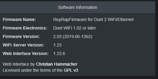
-
Hello,
I think you have to send G29 S1 to enable the mesh compensation and to load height map from file. In your config there is only the G29 to probe the bed and save height map to file -
so if I am understanding correctly when I run G32, it runs G29 based on the bed file. Then once it is complete I save the map using M374 P"glassplate.csv" I then put in the slicer startup M375 P"glassplate.csv" which should load the save map. but since I am missing G29 S1 it is not enabling mesh composition.
What I really need is to put G29 S1 P"glassplate.csv" in the slicer start code to get it enabled, right?
-
Hi there,
In fact you could run the mesh compensation with G29 S0 just once. After that the heightmap is saved. In your start gcode just then just need the command G29 S1 to load the saved heightmap. That's it, works perfect for me!")
After some prints if you see that the compensation isn't perfect anymore you just run the mesh compensation again with G29 S0 and your good again.Best,
Markus -
What do you have in your homeall file?
It looks like you are doing your homing moves directly in the slicer start code. It would be better to simply call G28 there so that homeall.g gets run.
You don't need to use M401 or M402 in your files. The firmware will handle the pin deployment as needed.
When are you running G32? And where are you saving the file glassplate.csv?
The idea of saving different height maps to recall after switching the bed surface is nice, but it has the flaw that once you have physically altered the bed surface, you will likely need to rerun the G29 mapping again for it to be truly accurate. Unless of course you have a bed surface mounting mechanism that guarantees repeatability.
-
I actually tried just doing homeall in the slicer code then individually but it did not behave as expected. I am running G32 befure I start a print and saving glassplate.csv to the sd card. I have since changed to saving it as a default just to keep it simple as changed3d gmbh stated.
Homeall.g file
; homeall.g
; called to home all axes
;
; generated by RepRapFirmware Configuration Tool v2 on Sun Mar 17 2019 11:31:51 GMT-0400 (Eastern Daylight Time)M561 ; Clear any Bed Transform
G91 ; relative positioning
G1 Z5 F6000 S2 ; lift Z relative to current position
M401 ; deploy mechanical Z probe
G1 S1 X-335 Y-335 F1800 ; move quickly to X or Y endstop and stop there (first pass)
G1 S1 X-335 ; home X axis
G1 S1 Y-335 ; home Y axis
G1 X5 Y5 F6000 ; go back a few mm
G1 S1 X-335 F360 ; move slowly to X axis endstop once more (second pass)
G1 S1 Y-335 ; then move slowly to Y axis endstop
G90 ; absolute positioning
G1 X171 Y112 F6000 ; go to first bed probe point and home Z
G30 ; home Z by probing the bed; Uncomment the following lines to lift Z after probing
;G91 ; relative positioning
;G1 S2 Z5 F100 ; lift Z relative to current position
;G90 ; absolute positioningM402 ; retract mechanical Z probe
-
@jaurand said in Bed Composition does not seem right:
M401 ; deploy mechanical Z probe
M402 ; retract mechanical Z probeRemove those as well.
-
Your height map looks good. Assuming that you did the print immediately after probing and getting that height map, my guess is that you are using a Z probe that is offset from the nozzle, and the tilt of the print head varies slightly along whichever axis is top to bottom of your print photo. This tilt changes the relative heights of the nozzle and the Z probe.
Duet WiFi hardware designer and firmware engineer
Please do not ask me for Duet support via PM or email, use the forum
http://www.escher3d.com, https://miscsolutions.wordpress.com -
@dc42 bltouch is offset from the nozzle, onjave linear rails for x and y axis so shouldn't vary much but maybe it's a bit of wobble in the head as the belts pull on the carriage
-
To verify that my prints actually use bed compensation I stick an adhesive tape 'flag' to the top of the Z screw and verify that it turns slightly during x/y movements of the print.
Your bed looks very flat and level but you can play with the screws to have larger error and make the Z flag movements more visible.