Mesh leveling: should we see the Z axis value change in DWC?
-
Hello to all:
Machine: CoreXY (300x300), with Duet2 2.05 and DWC 2.07
config (1).g homeall.g
The bed is a 1/4in MIC 6 tooling plate with a 3 point (manual) leveling system:once leveled it was fine for over a year, I used no compensation. Z axis was homed using an optical end-stop, still is.
I just changed my printing surface (magnetic) from Geckotek to PEI and decided to add an original BL-Touch to my setup . I plan to create a map once, and load it at print time.
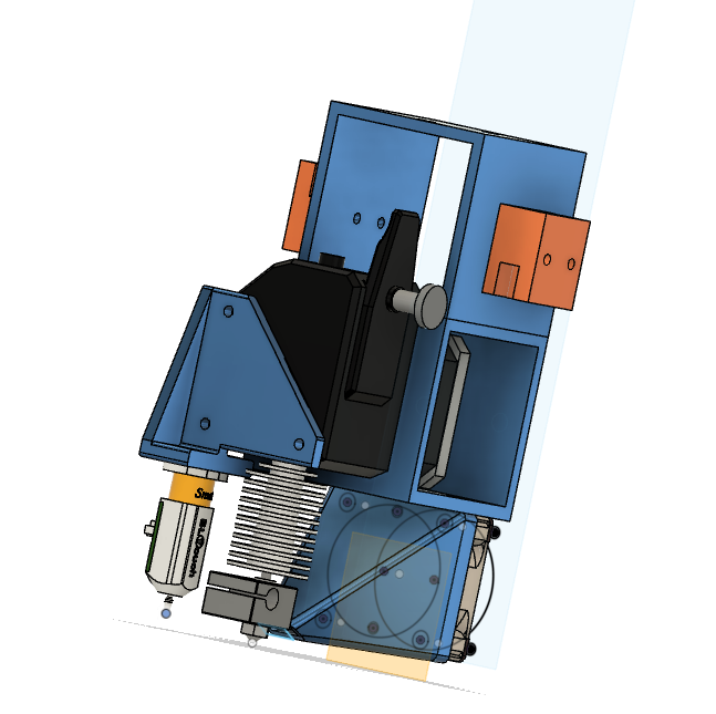
I have proceeded very slowly with this step as I do not want to damage my new print surface... The BL-Touch is precisely placed via a bracket I printed from the Fusion360 CAD model I prepared for my printer.
I have had no issues and I believe all the proper steps are in place for the mesh leveling. I searched this forum for information and actually found a tip for the M558 (thanks ...).
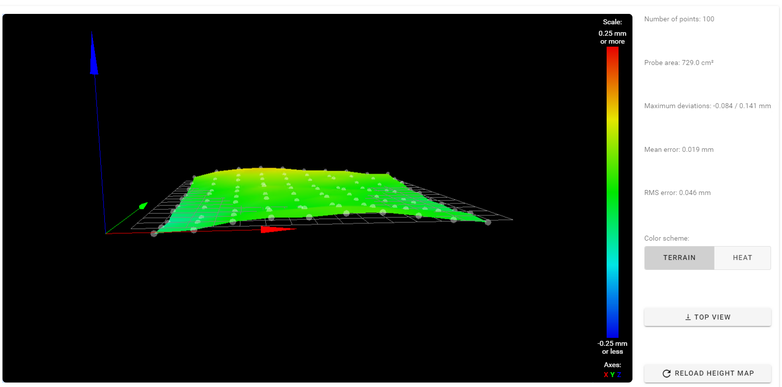
As you can see from the leveling map, no major problems with generating the map (multiple repeats to make sure all is ok). The slight warp towards the back is verified with manual measurements, so the map itself seems ok.
I have done a few tests <air printing> a few mm above the bed a test pattern that runs near the edge of the build plate (actually a 280x280 square) which is right at the edge of the probing area. A M122 while printing confirms that the map is loaded.I would expect the Z axis position shown in the DWC to change a bit at the head moves around the bed, but the number does not change, and I see (and feel) no movement on the Z-axis.
Enclosed are my config.g and homeall.g files.
From the Homeall file (last commands sent):
;###########################################################################################
; Use Mesh leveling
G90 ; absolute mode
G1 Z10 F600 ;move down bed
G1 X170 Y164 F6000 ;move <probe> to the center of bed (150,150) (not the nozzle)
G30 ;probe bed to establish Z position (set to Trigger height defined in config.g)
G29 S1 ;load mesh map from SD card
;M376 H5 ;compensate within 5mm Z height taper
;###########################################################################################From the config file:
; ############## Z-Probe ##############
M307 H3 A-1 C-1 D-1
M558 P9 H5 F100 T6000 A10 R0.75 S0.003 B1 ; P9 for BLTouch, dive height 5mm, probe at 100mm/min, travel 6000mm/s, up to 10 probes, pause 0.5s, heaters off
G31 X-20.0 Y-14.0 Z1.85 P25; ############## Define mesh grid ##############
M557 X5:285 Y5:285 S30 ; Define mesh gridSo, should the Z axis be moving to adjust the first layer height with this map in place ?
What have I missed ?Any input will be greatly appreciated.
François -
@msjfb said in Mesh leveling: should we see the Z axis value change in DWC?:
I would expect the Z axis position shown in the DWC to change a bit at the head moves around the bed, but the number does not change
No, the mesh compensation is exactly that for. Lets say your first layer heigh is 0.2 mm, then whereever your nozzle is in xy plane, z should be always 0.2 from bed and you cant see any changes in DWC. However, you should see actual Z movement if it need alot of compensation. And of course it depends on what leadscrew you use for Z. If i am wrong here, then i hope smarter users will correct this.
-
Just FYI...It looks like you already do this but all axes have to be homed before you load an existing heightmap or it won't have any effect.
If you use baby stepping or small Z jogs equal to the expected correction, can you see or feel the movement?
-
The value in DWC is just showing you the distance from Z0. And the heightmap is correcting Z0 for all positions on the bed.
If the Z motors are not turning at all during your airprint, it could be because you have a 5mm taper set. So if you are close to 5mm or above, there would be very little movement.
The best way to test the effectiveness of the mesh compensation is to print a test file like this one twice. Once with mesh comp enabled, and once disabled. You should be able to tell the difference.
-
@gtj0
In the slicer startup Gcode, I call G28 . The code is in the enclosed homeall.g file: I home x,y,z (z with the optical endstop). Then I move to the center of the bed, call G30, then G29 S1. printing starts from there. So I think this is the correct sequence.@Phaedrux
During my 'airprint' the system thinks it is at Z=0, and I have commented out the Taper command. Here is what I do: I place a 10mm high cube at the center of the bed... then in the homeall.g I lower the bed to 40mm (instead of the 15mm seen in the homeall.g file before moving to the center (clearing the block), and call G30: the probe hits the block 10mm above the actual bed and Z is set at the trigger height. This way the nozzle is above the bed but the system thinks it is at 'the proper place'. Of course plastic is just pouring out but I am protecting my print surface from any unforeseen movement from the nozzle that would otherwise scratch or crash into the surface while I observe what is going on.
I will look at your STL file. Thanks.BTW I use a belt driven Z axis, easily accessible, so I should be able to feel the slightest movement with my finger on the belt (at least I think I should).
I may just tilt my bed, say 1mm, so that the compensation would have to be very apparent...Thank you for your comments, I will report back after a few tests.
-
Your largest correction is 0.141 and I would think that'd be difficult to see in a belted Z arrangement actually. That is assuming that the belt travels 1:1 with Z movement.
@Phaedrux 's right, a test print is the real way to determine if it's working or not.
-
@msjfb said in Mesh leveling: should we see the Z axis value change in DWC?:
The BL-Touch is precisely placed via a bracket I printed from the Fusion360 CAD model I prepared for my printer.
Does this mean you're using the CAD model for getting the G31 offsets? or have you measured those physically as well?
-
@Phaedrux
I have checked with a ruler, and it looked to be right on (20mm and 14mm)
I picked up models for the BL-Touch, BMG extruder and E3D V6 and included them in my CAD design. I have used this to align cooling fan, etc.
Here it is:
I guess I could make an imprint (fun-tak) with the nozzle and probe tip and measure that... -
Check these steps out for measuring the offsets. https://duet3d.dozuki.com/Guide/Ender+3+Pro+and+Duet+Maestro+Guide+Part+5:+Upgrades/54#s230
-
I am pleased to report that in the end, all was OK with the settings: the mesh map was indeed properly loaded and used. Because of my setup minute Z axis movements are all but impossible to detect.
So, here is what I did to check it:
- Checked that my offsets were correct , per @Phaedrux suggestion: my numbers were spot on!
- Since I have a flexsheet, i created a 'bump' in my bed of approx 1mm height.
- Created a map, loaded it and 'air printed' the test lines: sure enough I could now see the axis move when crossing the 'bump'.
- Next I created a more realistic deviation, approx 0.1mm , ran a new scan and loaded that new map.
- Printing (on the bed) without mesh correction I could clearly see the layer flatten over the bump, and with correction it was essentially perfect.
Thanks to everyone that gave me a hand on this.
I am now moving to another issue: with mesh correction active, how to adjust the actual distance between the nozzle and the bed when printing with different materials for instance: higher up for PETG, and lower for PLA for instance.
I have started testing , and I need to search this forum a little more, but I will probably open a new topic for this.François
-
@msjfb said in Mesh leveling: should we see the Z axis value change in DWC?:
I am now moving to another issue: with mesh correction active, how to adjust the actual distance between the nozzle and the bed when printing with different materials for instance: higher up for PETG, and lower for PLA for instance.
I have started testing , and I need to search this forum a little more, but I will probably open a new topic for this.There's a few ways.
You can use babystepping at the start of the print to adjust the Z height up or down by small amounts manually.
You can set a Z offset in the slicer. There's usually an option to add a small amount for the first layer.For what it's worth though, I never actually do this anymore. My first layers are always the same, regardless of material being printed. I print on heated PEI and the only thing that changes is the temperatures, and for PETG I add some glue stick as a release agent. The first layer is always 0.2 and the extrusion width is always equal to the nozzle diameter and 30-35mm/s. The PEI is pretty flat but I do a detailed mesh compensation anyway and the first layer is always spot on, no offset or over extrusion.
-
Before enabling mesh leveling, I would use the G92 Zxx command in homeall.g to adjust the height above the bed, if needed.
My concern was that I may not be able to use this method once I started using mesh leveling.
After reading up and searching this forum, I have come to the (right ?) conclusion that I can use this method if I need to.
Here is my understanding of how to use mesh leveling:- First you determine a Trigger height with a probe (G30 S-1) at a specific point, bed heated up, and enter it in the config.g file (G31 Zx.x): in my case 1.95mm.
- Then generate a mesh map by first probing (G30) at the same point on the (heated) bed and then starting a bed probe (G29 S0).
At print time, to use mesh leveling, add in the homeall.g file:
- Home X,Y,Z
- Move to the same probing point as above, heat the bed, and do a G30 probe, i.e. same conditions as when the map was generated.
NOTE: The current trigger height must (???) be the same as the one in effect when initially generating the map. - Load mesh leveling map with G29 S1
- Move back to origin before starting a print.
NOTE: in my case the nozzle is now at 4.95mm (3mm dive + 1.95 trigger height)
-->It is here that I think I could modify the Z height with a G92 command if I wish to adjust distance to bed AND still ensure that the mesh leveling map will do its job correctly.
Is this correct ?
Suggestion: when creating the mesh leveling file, save the trigger height value to the file( simply as a reference).
-
@msjfb said in Mesh leveling: should we see the Z axis value change in DWC?:
It is here that I think I could modify the Z height with a G92 command if I wish to adjust distance to bed AND still ensure that the mesh leveling map will do its job correctly.
Don't use G92. It shouldn't be necessary if your trigger height is correct. If you're homing files use an endstop switch the exact position isn't really important as long as you're using the probe to define the bed Z0 before the heightmap is loaded.
If you do need to adjust the Z height, use baby stepping instead. It will shift the position of the physical head without changing the coordinate position.
-
@Phaedrux said in Mesh leveling: should we see the Z axis value change in DWC?:
If you do need to adjust the Z height, use baby stepping instead. It will shift the position of the physical head without changing the coordinate position.
That's what I wanted to clear up.
Thanks for your tips and explanation.
François