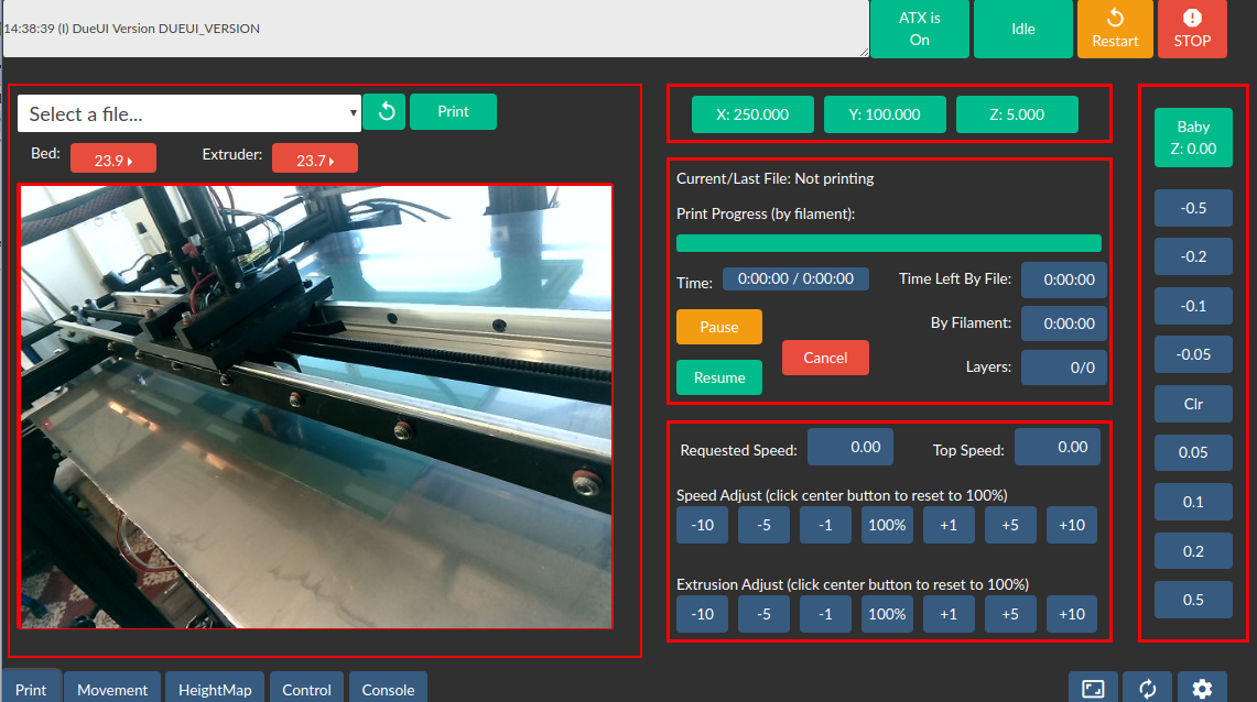
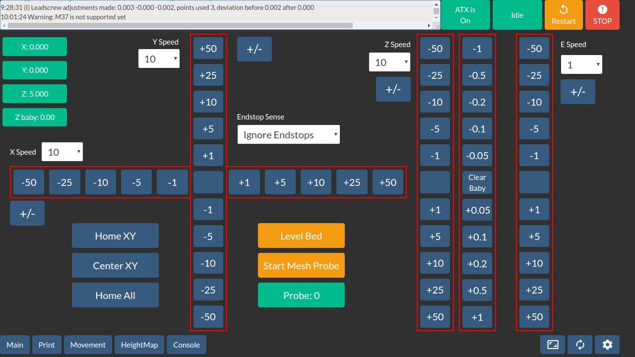
I feel like the guy who builds a boat in his basement or the classic car guy who spends more time working on his car than driving it. Anyway, I started build Black Beauty a few years ago and although I've done plenty of printing, lately I've been working on the software side of things. A few weeks ago I realized I needed to get back to actual printing but thought Black Beauty was looking a little rough around the edges and could do with some minor work. Then it occurred to me that having all the wiring and electronics on the back of the printer just didn't look right. That turned into a complete re-wiring job.
So, this is what I wound up with...

The whole assembly is elevated to allow good air flow and there's a cover that sits on top of the whole thing.
Mains enters at the back and all mains wiring stays at the center back. Luckily the two power supplied cooperated by having their mains terminal towards the center. Low voltage exits the power domain to the left and right and never crosses mains wiring.
Back left to right
- 5V6A 12V3A PSU. This provides 5V to all electronics and 12V to my touch screen monitor.
- The two SSRs switch the mains powered bed and the 24V21A PSU.
- The 24V PSU has a blower fan on top pointing to the right.
Front right to left
- The SBC I'm using is a Jetson Nano.
- There's a small USB hub that connects the Nano's serial and debug ports to my development machine for testing purposes.
- The ribbon cables on the right side of the Nano connect to the Duet3's 26pin header and provide 5V power to the Duet3 and the serial uart on the Duet3 connects back to the Nano for diagnostic purposes.
- The Nano has a network cable of course but also connected is the USB camera, the Duet3's USB port, and my touch screen monitor (HDMI and USB).
- You can figure out what's connected to the Duet3 by looking at it.

- The RJ45 connectors on the left go to the bed (temp and LEDs), tool carriage(temp, probe, endstop) and my manual emergency button box.
Here's a wider view:

The control box, from left to right:
- The latching stomp button connects to the reset header on the duet.
- The paddle switch turns 5V to the Duet3 on and off.
- The green button is the power button for the Nano.
- The red button is the reseet switch for the Nano.
Here's what the top end looks like now although I have a feeling it'll need some "minor" work as well 

And in all its glory:

Look nice and neat huh?
Here's what my workspace looks like: 


