How to setup the Bigtreetech smart filament sensor?
-
@arhi said in How to setup the Bigtreetech smart filament sensor?:
To test the U1 on it's own you can bring Vcc to pin1 and expect 0V on the pin6 and also Vss to pin1 and expect 5V on pin6, just to be sure the U1 is not dead. Shorting U1-1 to Vcc or Vss should not damage anything.
I'm not exactly sure what you mean by this. Should i bridge Vcc or vss to U1-1 then measure over U1-6 and Vss?
With 5V I get a 1,7V pulse so that should be high enough however i'm getting a constant 1,3V on the output now
-
@Infinitysnek said in How to setup the Bigtreetech smart filament sensor?:
I'm not exactly sure what you mean by this. Should i bridge Vcc or vss to U1-1 then measure over U1-6 and Vss?
yes.
With 5V I get a 1,7V pulse so that should be high enough however i'm getting a constant 1,3V on the output now
I fear that U1 is dead. The schmitt output can only be 0 or Vcc (with a very little offset), the output of 1.3 on the 4 or 6 pin should only happen if you power it from 1.3V
-
@arhi Well thats too bad. The chips is fairly cheap at €2 for 20 so ill get some and replace the chip when it arrives in a month or so.
It is impossible for me to bridge the 2 pins and probe 2 others at the same time so Im going to assume its dead.Thank you for your help so far I really appreciate it

-
double check if those outputs go really directly to the connector trough 200R or maybe they have some other links that you missed but on the output pins really you should not see anything except 0/1 (Vss/Vcc).
Also, if you have any other schmitt inverter you can bodge it there.. should work..
-
@arhi I will check tomorrow. I don't have any schmitt inverters laying around but I did found another online: NC7WZ14P6X. Seems similar and should be here within a week.
-
@arhi I was going to replace the chip today until i found out its even smaller and doesn't fit

I ordered new ones but that will take a while to arrive...
-
if its pin-compatible you could try stretching and bending the legs to force it onto the bigger pad.
(apply liberal amounts of "carefulling" first)or solder thin wires from the pad to the leads. if current situation means huge delays I'd be inclined to try it.
edit: i've only had to use bigger chips on smaller pads, but having given it a second thought I'd flatten the legs to they come straight out the side of the chip to make up the missing length, angle them outwards to align with the pads, then just solder a wire between the pad on the board and lead of the chip that would otherwise be floating in air. once you got one down the rest should be simple-ish.
-
uh, I hate when it happens...
@omni will bring his one to me these days ('cause mine is not arriving for months now
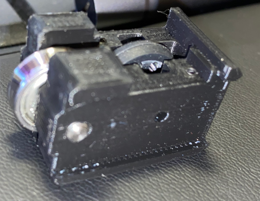
) so I can do some real life testing here ... I finished the new "case" for my encoder last night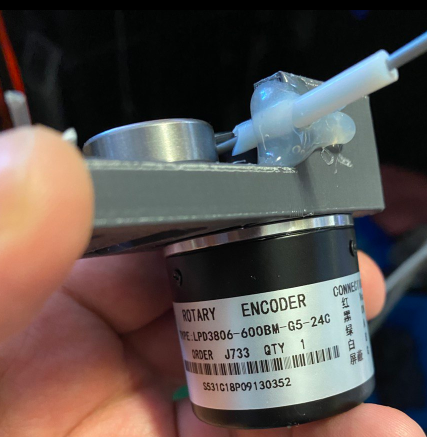
it's not a fancy package like the btree sensor but it does not restrict filament flow as much as btree one does and it's 600 impulses per rotation so ~8 impulses per mm instead of 1 impulse every 7mm
") and these encoders are 5-6eur delivered so 3x cheaper than btree one
and these encoders are 5-6eur delivered so 3x cheaper than btree one anyhow I'm waiting for the tests you do after you replace the chip.
btw, one quick test you should be able to do during the weekend .. if you have hotair gun, heat it up a bit and just lift the pin1 and pin6 from the pcb so they don't touch any of the circuitry ... power the chip with 5V and measure output on the pin6 when you short the pin1 to ground and to 5V (should be easy to just solder a jumper wires so you can easily measure) just to be 100% sure that chip is dead ... or if you already desoldered it (I think you did), just solder the 4 wires (1,2,5,6) and try "in the air" ...
and I agree with @bearer few wires and that small one can fit, I did it more than once and still hate doing it but it's a fairly quick job if you have a steady hand and ok-ish vision
-
I have desoldered the chip already yes. I could try soldering on wires, hated doing that last time for a different project but it’s better than waiting a few weeks for new chips.
Does yours work with the duet? If this won’t play nice with the duet I could repurpose the housing for something like that
-
@Infinitysnek said in How to setup the Bigtreetech smart filament sensor?:
I could try soldering on wires, hated doing that last time
Useful hint, how I do it if I don't want to make a breakout board pcb - hot-glue
Put some hot-glue on a plate (wood, plastic, cardboard...) and put the chip on its back on that hot glue. This way the chip is held in place, the legs are up in the air much more accessible when the chip is "back up" compared to "back down". Use "magnet wire" (lacquered wire from a transformer or similar device). With some practice, you can even make whole circuits using that (dead bug) technique.
Does yours work with the duet?
Yes, I had it connected to duet for a while with old design I made, it was disabled but collecting data. Problem was that old design was not very good (not sure if new one is much better we'll see) so the filament got tangled few times and almost ruined the print so I redesigned it and will be adding it back on the duet. This encoders have Vcc, Vss, A and B outputs (AB is from encoder) and I'm using A to send signals to duet and it was working good. What I don't remember is what I used for Vcc :(, IIRC this thing has 7805 inside so can be powered from 6-12V. I have one DCDC hooked on my duet2 to produce 12V for various needs but no clue if that's how I was connecting it. I'll play with it on Sunday again so I'll make a separate post about how it works if anyone wants to use the same el-cheapo encoder from PRC (hoping someone will make a better housing for it
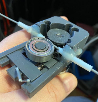
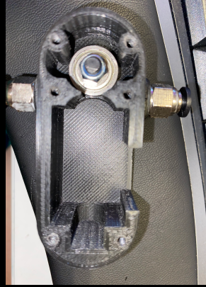
.. here if you can see from the images the 608 bearing slides on some rails, is pressed by the spring between that slider and external slider and externan slider is locked in place by the hole on the rail and piece of filament in that hole .... on the encoder's shaft I press fitted the printed wheel with concave edge and a wide rubber band wrapped around it to give it "grip" ... I glued the ptfe guide's 'cause during design I had no clue what the position of the wheels will be and after I did it was faster to just glue it in place than to change design and add more material with holes for those tubes -
Soldering wires wasn’t really a succes so I’ll wait for the other chip to arrive
-
-
-
The only thing I'm unsure about is the foto sensor as I never seen PNP foto-transistor, nor I seen them in this dual packages before. Normally they are NPN and single package but the way it is connected I have to assume this is PNP.
Now, Vcc - GND, I tested 5V and 3.3V and both work perfect.
The out_X is already push-pull so you do not need any pull-up/push-down on the IO pin on duet. And no need for resistor dividers, only power the sensor from 3.3V and you should be golden.Have not yet connected to my duet but scope shows impulses going ok.
I have to say I don't get the construction?!?!
- the spring (at least in the one that @omni brought here today for me to test) is so damn strong the sensor deforms the filament and makes it very hard to pull. Not a big deal if you are running BMG but cmon, there's no need for this, the original spring must go away and to be replaced with a softer one
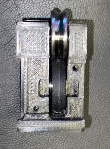
- there is a fixed idler bearing with V grove ?!?!
normally you make this idler moveable so it presses on the drive gear, but they decided to make this bearing static and to move the whole block with electronics, connector... to press the filament ?!!? WEEEEEEIRD
- then, instead of encoder wheel (with rubber outside ring, soft and sticky to grab the filament easily) having contact with the filament, they add another bearing between encoder wheel and the filament, another V groved metal bearing that have zero grip on the filament (probbly why the spring is so strong so filament don't slip on the smoth side of the bearing)
So, to "fix"
- replace the spring with something softer
- need to add grip on the bearing in the slide-block, I assume a small wide rubber band will do the trick (those used for money wide ones are great)
To connect:
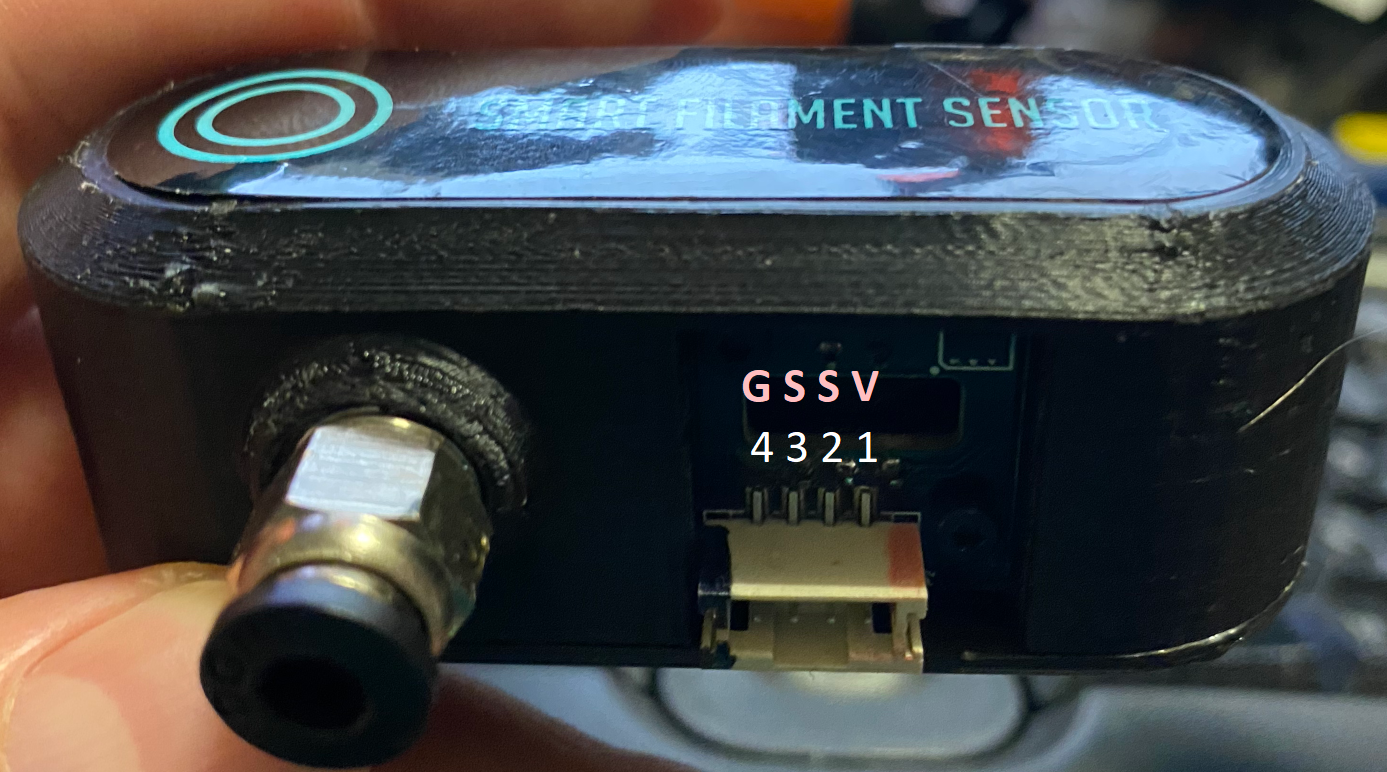
Pin closes to the bowden coupling is Ground, than there are 2 output pins and the pin farthest from the bowden connector is Vcc. Connect Vcc to 3v3, Ground to Ground, one of the output pins to the E_stop and that's it
-
and, def. works

need to be now properly configured (this is configured for my encoder) but to get you started
M591 D0 P7 C"e0stop" L0.5 R90:110 E3 S0now you need to setup your own L value and your own span .. for start it's disabled but will collect data, when you are happy with the way you calibrated it you enable it and enjoy
@omni 's U1 was not dead, I'm not sure how was he connecting it when it was not working but he did not burn the U1 so I just retraced the whole schematic (I desoldered the photo transistor pack to test it separately and make sure it's not ghosting my schematic, and then put it back after I was done, tested transistors separately with IR transmitter from a remote controller
)All in all, it works directly from 3v3 so all pins you need are on the E0STOP and E1STOP connectors on duet2ethernet (I assume the other duet's have similar/same connector)
-
Thank you for your extensive testing!
Looking at your schematic do you think I could have blown up U1 when it was wired up wrong? I still have the desoldered chip and assuming I did not damage it during desoldering I could place it back.Does it anywhere say what your board version is? I notice the housing for the one you have is 3D printed while mine is injection molded. Maybe they changed the spring too, mine is certainly stiff but does not deform the filament, there is some noticeable resistance to get it going but it rolls smooth after that. I do wonder if the stiff spring will be a problem with flexible filaments.
-
@Infinitysnek said in How to setup the Bigtreetech smart filament sensor?:
Thank you for your extensive testing!
I ordered this filament monitor myself (stuck in the post somewhere for months
) and I'm helping out @omni to migrate to duet and upgrade his printer and he's using this monitor too so it's for selfish reasons Looking at your schematic do you think I could have blown up U1 when it was wired up wrong?
Looling at the documents from btr they put there GSV and not GSSV so if you really pay attention you see on the images that there is a wire missing between S and V on their image but it's visible only if you really know what to look for, normally it looks like GSVx and in that way you power the output of the circuit. There's 200R on the output but it could maybe kill that PRC clone of the dual schmitt trigger.
omni also connected the device wrong but it is working ok, the U1 did not die. What did you power it with? 5V? 12V?
I still have the desoldered chip and assuming I did not damage it during desoldering I could place it back.
I doubt you can kill it by desoldering those can survive a lot of heat, but you measured something other than Vss/Vcc on the 2-3 pins and output of schmitt trigger cannot float, it's either 0 or 1 hence me assume that U1 is dead.
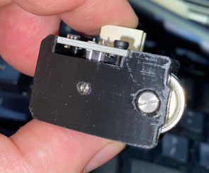
Does it anywhere say what your board version is? I notice the housing for the one you have is 3D printed while mine is injection molded.
Yes, @omni's sensor is 3d printed case. PCB is v1.2
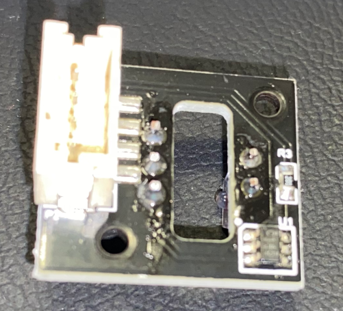
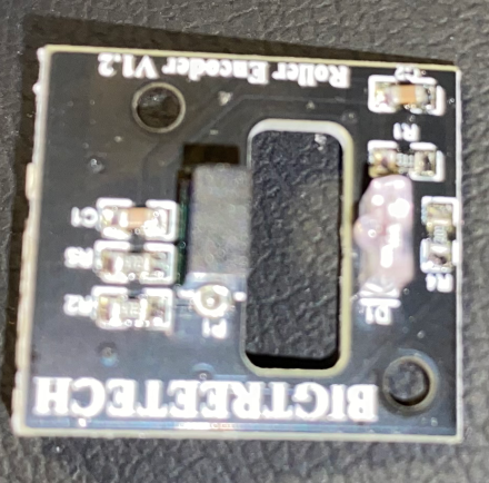
sorry images are total %$#%^@ I was not looking if they are in focus I assumed stupid iphone will focus properly
Maybe they changed the spring too, mine is certainly stiff but does not deform the filament
I pressed this one few times fully and now it does not deform filament any more but it still offer way more resistance than I'd like
there is some noticeable resistance to get it going but it rolls smooth after that. I do wonder if the stiff spring will be a problem with flexible filaments.
this one will be but it's super easy to replace so I'm sure omni will do it... it's more that whole design is imo wrong, the connector slides instead of bearing, the additional bearing between wheel with holes and idler, no rubber on the drive wheel.. dunno, makes no sense to me really, I expected much more refined design
-
@arhi said in How to setup the Bigtreetech smart filament sensor?:
What did you power it with? 5V? 12V?
Only 3V3 and 5V never any higher.
Since I have to wait anyway for a replacement chip could I measure on the pins for resistance to check? Otherwise I'll just going to solder it back and hope it magically fixed itself.
-
@Infinitysnek said in How to setup the Bigtreetech smart filament sensor?:
@arhi said in How to setup the Bigtreetech smart filament sensor?:
What did you power it with? 5V? 12V?
Only 3V3 and 5V never any higher.
omni did the same and did not kill it
Since I have to wait anyway for a replacement chip could I measure on the pins for resistance to check?
Nope, you need to power it on to test it.
Otherwise I'll just going to solder it back and hope it magically fixed itself.
it is easiest way to test it, you can easily remove it if it does not work.
When you power it (3.3V enough) irrelevant to what input is, output (pins 4 and 6) must be either ground or vcc, can't be nothing in between, if you measure something in between it is dead. BUT make sure you keep the sensor in dark when you are measuring as if the sensor is picking up some noise it could be turning the input on/off quickly that will then translate to output going quickly between Vcc and Vss and since you are measuring with DMM and not a scope you will get some RMS value that will be between Vcc and Vss. So put some metal cap over the transistor when measuring outputs
-
@arhi said in How to setup the Bigtreetech smart filament sensor?:
@Infinitysnek your schematic was very close to the real thing
...here's my take
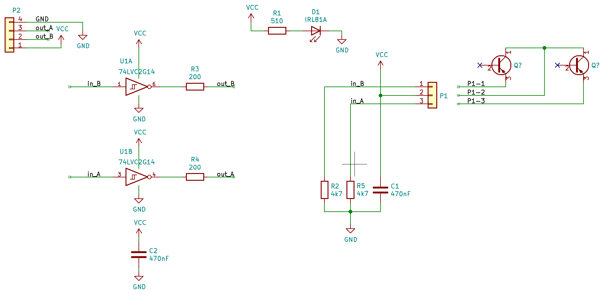
The two phototransistors will be NPN, but otherwise that looks highly plausible. In which case, it has quadrature outputs, so by using two inputs on the Duet and appropriate firmware it would be possible to sense direction of filament travel as well as amount.
Duet WiFi hardware designer and firmware engineer
Please do not ask me for Duet support via PM or email, use the forum
http://www.escher3d.com, https://miscsolutions.wordpress.com