Endstop - wiring
-
Hey,
I try to connect a 2 normal Chinese endstop to my duet 3 (x/y) which has 3 wires. G, U and S.
I have it on io3.in.
Which pins do I have to use?
Thanks -
@barbarossa-cologne
normal Chinese endstop
Do you mean microswitches? If so, see https://duet3d.dozuki.com/Wiki/Connecting_endstop_switches#Section_Microswitch
Otherwise, a picture may help.
Ian
-
@droftarts
sry I´m not sure...
Before I damage something I wanted to clear the rigth wiring.(
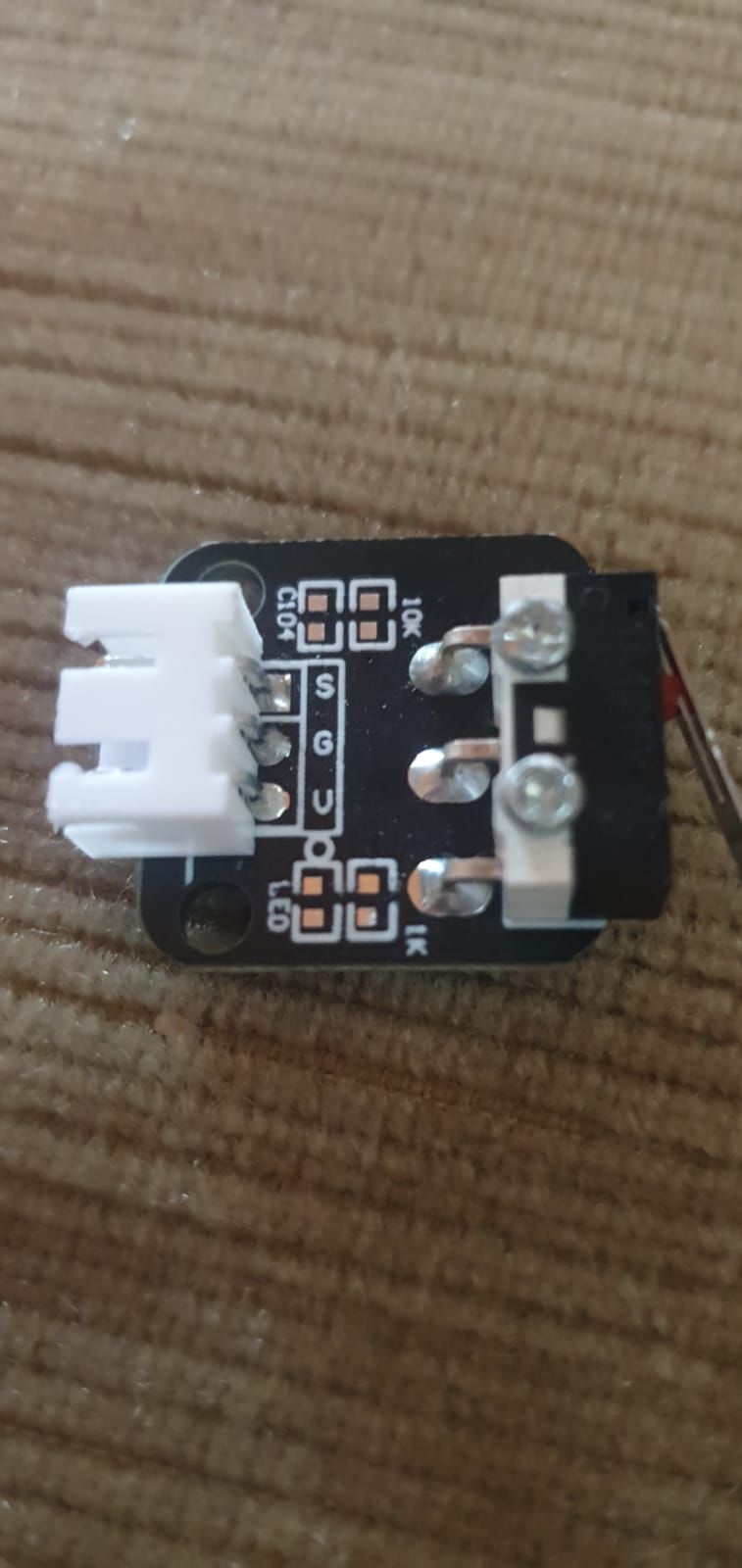 image url)
 -
@barbarossa-cologne I'd guess that was 'S'witch, 'G'round and 'V'oltage. In which case, try wiring it up like this: https://duet3d.dozuki.com/Wiki/Connecting_endstop_switches#Section_Makerbot_Mechanical_Endstop_v1_Num_2
... though the board doesn't seem to be populated with components?! Often these sort of boards have an LED to show when they're triggered. Anything on the other side of the board?
Ian
Bed-slinger - Mini5+ WiFi/1LC | RRP Fisher v1 - D2 WiFi | Polargraph - D2 WiFi | TronXY X5S - 6HC/Roto | CNC router - 6HC | Tractus3D T1250 - D2 Eth
-
@droftarts
there is nothing on the backside... my settings are on activ-high
; Endstops
M574 X2 S1 P"!io3.in" ; configure active-high endstop for high end on X via pin !io3.in
M574 Y2 S1 P"io0.in" ; configure active-high endstop for high end on Y via pin !io0.inI connected like you said, but its still not connected

U - 3.3v
G - Ground
S - io.3in -
Those switches are usually wired like this :
U(V) - NC
G - NO
S - Comm.
As your switch doesnt have any components populated, you can leave U not connected and connect just G to ground and S to io.in and it should work as NO switch. -
@aidar
ok its working, but how can I change that the trigger is when the stop closes and not like now... I have to press the stop and it stops when I let the stop free.
thanks a lot -
I think you have to invert pin by adding (or removing if you already have it) ! mark in M574 command.
Another way is to use it as NC switch (recommended) instead of NO. To do so connect U to ground and leave G not connected. But remember for future - dont do that if you have any other components populated. It works only if you have only microswitch on that switchboard and nothing else!