Robotic kinematics
-
@droftarts said in Robotic kinematics:
only thing that isn't clear from the pages is that this is a fork of RRF, and not part of the main RRF release
I'll make a remark. Thanks for checking the pages.
-
@miss-rebekah I reviewed the robot documentation and changed the M669 A parameter a bit, please check whether your config preparation is current. Please tell me whether you can understand the documentation or I should clarify parts of it. https://docs.duet3d.com/User_manual/Machine_configuration/Configuring_RepRapFirmware_for_a_Robot_printer
I'll finish the first firmware version the next two weeks and provide you with a ready-to-use Duet 2 binary. I can help you with configuration of your robot then, if you provide the information about the setup.
-
@droftarts could you please be so kind and remove a comment in https://docs.duet3d.com/User_manual/Machine_configuration/Configuring_RepRapFirmware_for_a_Robot_printer , in the title I cannot edit the second line "Currently for 4 to 6 axis robots". Maybe I am simply too stupid to find how I can edit it. Please simply remove the comment, as it is no longer correct.
-
@joergs5 when editing, click on
pageat the top right between save and close, its in there. I've removed it for you -
@jay_s_uk thanks a lot!!
-
I finished the robot kinematics about two weeks ago, but I have no good method to check whether the calculations are correct. What was missing, was a visual check whether the endpoint has the intended orientation.
I've started to develop a DWC plugin for this reason and to help finding the correct robot parameters. The result is https://forum.duet3d.com/topic/28492/robotviewer-dwc-plugin , the RobotViewer plugin, which allows DH parameter changes and seeing the consequences of changes. I'll enhance this version to cooperate good with the kinematics in the firmware.
-
I am enhancing the robot kinematics by closed chain and multiple chain kinematics, but I have a problem: I don't know how to define configuration syntax. Maybe someone has an idea or technical paper.
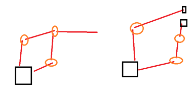
(the image is not nice, but license free!)The first case is closed chain like stewart, CoreXY, parallel scara. The second e.g. Open5 with top hotend and button the printed object, which will be rotated. The circles are the actuators.
An idea for multichain would be
(BPPPE)(BRRO) for two chains base-prismatic-prismatic-prismatic-endpoint, base-rotational-rotational-object, the base being the point which stays at it's place with unchanged orientation. The multichain should support multiple in the sense of fingers of a hand e.g.An idea for closed chain would be
B(RR3)(RR3)E
so it's clear that R3 is common and the closing chain, numbering only when necessary.
But Stewart would be very complex.It's also necessary to define how the chain is closed: matching the endpoints or additionally same orientation? Or specific angle?
Any ideas?
-
Some time since last update, so I want to give some update information. Had Covid and recovered, hope you are all well too.
Robot kinematics will be included in RRF 3.5, after talking with David and Tony. I have agreed to have a working version end of August, so the integration will start after this date.
I am currently working on
- performance optimizing and testing
- implementing additional kinematics like CNC 5 axis and 4 axis palletizing robots which are built like ABB IRB 460
- documentation. Starting point is https://docs.duet3d.com/User_manual/Machine_configuration/Configuring_RepRapFirmware_for_a_Robot_printer and I tagged the documents with robot tag, currently 4 documents. Detailed descriptions e.g. of orientation, RobotViewer, Config. Please ignore misspelling, but if you find logical errors, please tell me to correct it
- still working on a good prototype, but this takes eternal
-
@joergs5 said in Robotic kinematics:
still working on a good prototype, but this takes eternal
Good to hear you're well again!
I didn't read the whole thread, but I'm curious to know where to get all the stuff required to build one? Differential screws, optical encoders and lenses, all have to fit together...
I hope you'll add a BOM to your prototype
-
@o_lampe I'll make a BOM for sure. Nor for every screw, but for all main parts.
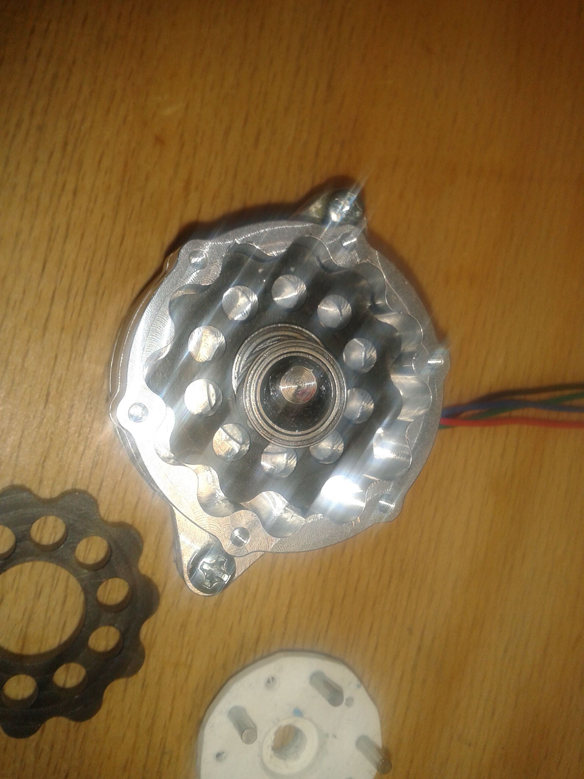
The main time it takes is for building harmonic drives, where I take two paths: one to 3D print the flexspline and circular spline, and one to use steel and drill the teeth. The 3D printed is meant to be that everyone can clone it, the steel one for a robot which can have higher payloads.
-
@joergs5 said in Robotic kinematics:
The main time it takes is for building harmonic drives,
I was pretty impressed by the cycloidal drive I made for a direct drive extruder. It would be even easier to scale it up for a robot.
Have you ever considered those?

-
@o_lampe that's a very nice looking one!
Yes, another user recommended using cycloidal gears in this thread somewhere above. It is an alternative. I've decided to go with harmonic drive, but there is no reason to consider cycloidal also. I love the cycloidal drives from Nabtesco like the RV500-N, which are used in Fanuc and ABB robots, but they have similar price ranges like the harmonic drives.
I standardize / modularize the components for myself, like the dimensions of the gears, so it will be possible to exchange harmonic drive, cycloidal or belt-based gears. I take dimensions of commercial ones as a guideline.
-
@joergs5 Is this work still active?
I wanted to take a look at the code to see what you're doing with the extra degrees of freedom, because I'm myself working on a modified hangprinter-like kynematics with 6 degrees of freedom. I only needed 6 steppers instead of 4 for the extra degrees of freedom, but I'm using 8 because I wanted to keep things squared and hopefully be able to get more speed with 8 motors, certainly I will have more torque.Anyway, the links to the code at the beginning of the thread are broken and I can't find it in your github account. Sorry I haven't read the whole read, but it's kind of long. Can you point me to the code?
Thanks in advance.
-
@jtimon I'm currently integrating it into RRF 3.5 locally and test, then will make a fork on github later this week. I removed my old fork. Hangprinter is also interesting, I would like to use it for wall painting (no joke), based on wires.
-
Before it's too late and the robot kinematics goes into the official RRF, I split the A parameter into A and D, because it was very difficult to keep overview of 10 parameters in one setting. Instead of one A parameter for DH and angle parameters, I define D for DH parameters and A for angles now.
Old eg:
A1:200.0:0.0:0.0:0.0:70.0:90.0:-180.0:0.0:180.0New eg:
D1:200.0:0.0:70.0:90.0
A1:-180.0:180.0:0.0I have to change firmware code, documentation and RobotViewer DWC plugin, which I do before making a RRF fork.
-
@jtimon sorry, it will take a few days more to deploy a RRF 3.5 version of the robot kinematics. I found a way to manage the different flavours of CNC 5 axis to be programmed, so I want to integrate it first.
Regarding hangprinter, do you know the site https://stadtfabrikanten.org/display/TH ?
The page "RepRapFirmware and calculations" is e.g. interesting regarding kinematics. -
@joergs5 Wall painting seems like a cool use case.
There are plenty of small projects doing that (or something similar):https://www.youtube.com/watch?v=_mTvSju3d6o
https://www.youtube.com/watch?v=T0jwdrgVBBchere's a CNC
https://www.youtube.com/watch?v=y60q6U7NjTQI'm currently working on adapting the hangprinter to allow more anchors in this PR:
https://github.com/Duet3D/RepRapFirmware/pull/585
But perhaps it would make sense to go lower than 4 anchors for some use cases too?
Thanks for the trikarus link, cool stuff.
Regarding your code, I'm not in a hurry. I'm not ready for working on the extra 3 rotational ABC axes since I still didn't get the basic xyz axes to work, and that is the part I want to read more, to see what you have done. Whenever you can share it, it would be awesome to have a look.
Thanks. -
@jtimon if you need help to understand firmware or how to address additional axes, I can help you, I have some experience now. I've created some documents about robot, starting is at https://docs.duet3d.com/User_manual/Machine_configuration/Configuring_RepRapFirmware_for_a_Robot_printer and made a tag "robot". The documents firmware and CNC 5 axis may be interesting for you about orientation.
I am constantly updating the documentation pages, when I think I have new knowledge to add.
Hangprinter may be a closed chain system, then robot kinematics will not help you much. You can check FiveBarScara, which is in the official RRF and uses closed kinematics, for additional code. I've used circle intersection in this kinematics to calculate the position of two arms without knowing the angles, this may help with wire based kinematics. Because you know the arm length (wire length), but not the angles.
-
@jtimon said in Robotic kinematics:
Wall painting seems like a cool use case.
There are plenty of small projects doingThank you for the links. I meant wall painting: a house wall, to save house scaffolding. But I will start in the house, a single wall. After all, most of the work is in the little nooks and crannies. These exceptions and path planning could be programmed and then executed with G-Code. A camera can control the result and repaint the locations where it is not good enough. Maybe spraying is better than painting then (a fixed orientation endpoint).
I first thought about using an industrial robot for wall painting, but long arms are a problem for high payload. But maybe one can combine hangprinter with robot: robot for orientation and placing to the correct location, hangprinter to support payload. It will be necessary to paint around corners.
-
I have a problem with understanding CNC 5 axis. If someone here has knowledge of CNC 5 axis, could you please tell me whether my understanding is correct? This is also valid for CoreXY 5 axis, Pentarod and Open5x.
I've described it in
https://docs.duet3d.com/en/User_manual/Machine_configuration/robot_5_axis_CNC
second section called "Calculation".My main confusion was reading an article about G-Code based on IJK (using tool vectors in G-Code) versus AC. The article wrote, an advantage of IJK is the machine independence. But in my understanding, AC is also machine independent (with the exception of the axis direction of AC versus BC). If someone knows if this is correct, a confirmation would be very kind.
