duet 3 connecting z probe inductive sensor
-
hey so im trying to get the z probe to work but im having trouble with it when i send the g30 code to set up and level. I cant find a wiring diagram to tell how to wire it. was wondering if anyone with a duet 3 has successfully connected and is using one of these inductive probes for the bed. i have the 3 wires from the probe connected to the following pins 5v power(brown wire) ground (blue wire) io5.in (black wire).
-
Ok never mind the resistors, I’ll try that out later but I just ordered another probe that is a npn swapped it out. It works just had to fix a couple wiring issues but anyone out there wanting to use a inductive sensor make sure it’s a npn inductive sensor, also the sensor works with the 3.3v power in the io5 pin and didn’t need to wire it to the vin or 12v. I have the brown going to 3.3v, the blue going to ground and the black going to “io5.in”. Well thanks for the help problem solved.

-
What is the specific inductive sensor you have?
Have you seen this?
-
I use a relay module. The sensor operates the relay and the relay switch output to the input, io3.in and ground on mine.
-
@Phaedrux I’m using a lj18a3-8-z probe. Bought it off amazon. When I put it against a piece of aluminum it’s red light turns on but I try using the g30 code and it says the sensor has been triggered before it even is near any metal surface. I’m not sure if I have it wired to the correct pins on my duet 3? Oh yes I have looked at that page on connecting the sensor but I don’t wanna short circuit anything and I also confused to what pin is used for the actual sensor wire, not the positive or negative wires.
-
This post is deleted! -
Your photo did not upload.
-
yeah never mind the picture, it was just the diagram of the duet 3 board. but im just lost on why its showing that error message?
-
Post your config please. It probably means that you need to invert the pin.
From the link I posted
Duet 3, you can connect the output of the sensor directly to the Z-probe IN pin. Connect the sensor ground wire to a ground pin on the Duet, and the sensor's + power wire to a suitable voltage (typically to VIN because these sensors usually need between 6 and 30V power).
Select mode 5 (P5) in the M558 command, also include parameter I1 in the M558 command.In the case of RRF3 the I1 to invert has been replaced by adding a ! in front of the pin name in the M558.
-
; Z-Probe
M558 P5 C"!^io5.in" H5 F120 T6000                   ; set Z probe type to switch and the dive height + speeds
G31 P500 X41 Y41 Z2.5                              ; set Z probe trigger value, offset and trigger height
M557 X15:215 Y15:195 S20                           ; define mesh grid
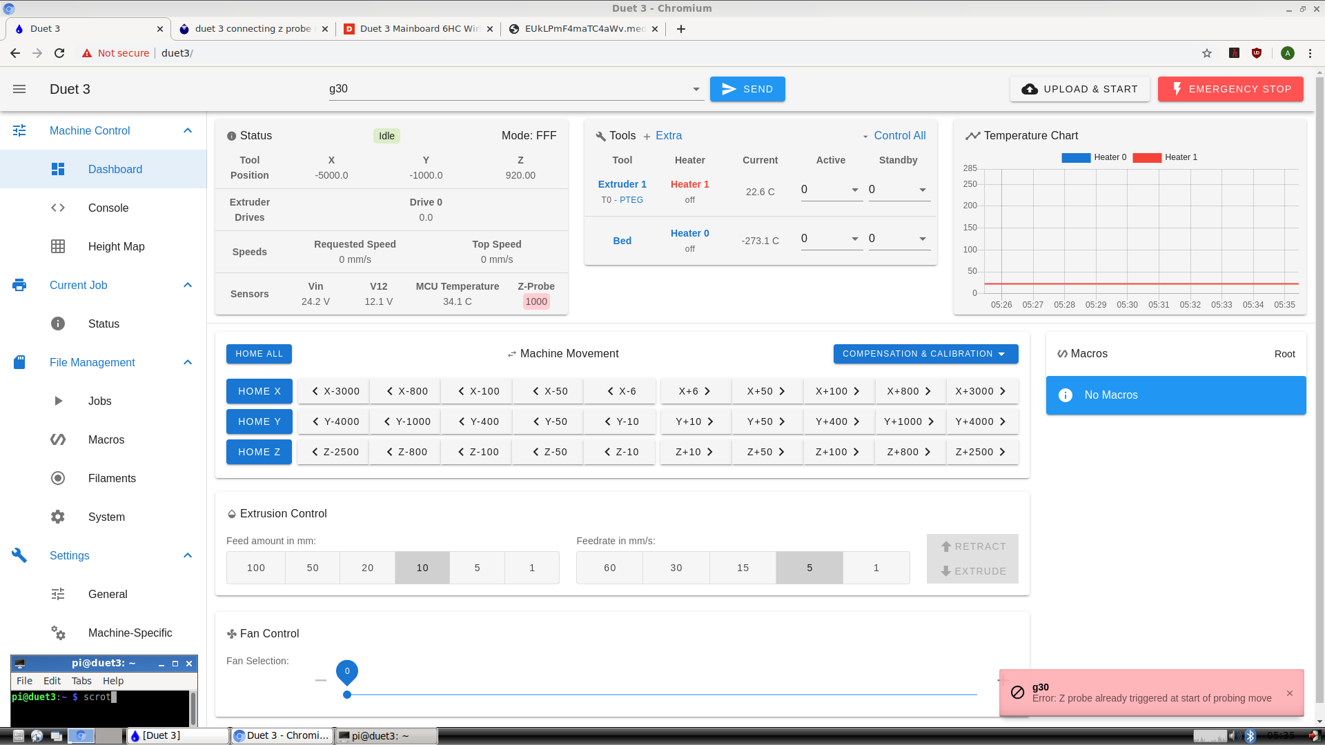
So, I added the "!" before the name of the pin Im using as you said to do and its now showing the value for the z probe as 0 now. but I send g30 and to test whether it would sense anything, I put a piece of aluminium against the sensor and it doesn't change the value to 1000 or show that its sensed anything below it. Im not sure why. The z axis is moving slowly down after sending g30 but it should stop and the value of the z probe reading on RRP should be 1000 if it senses anything, right?
-
@1997alex said in duet 3 connecting z probe inductive sensor:
C"!^io5.in"
Try removing the ^ to disable the pull up resistor.
-
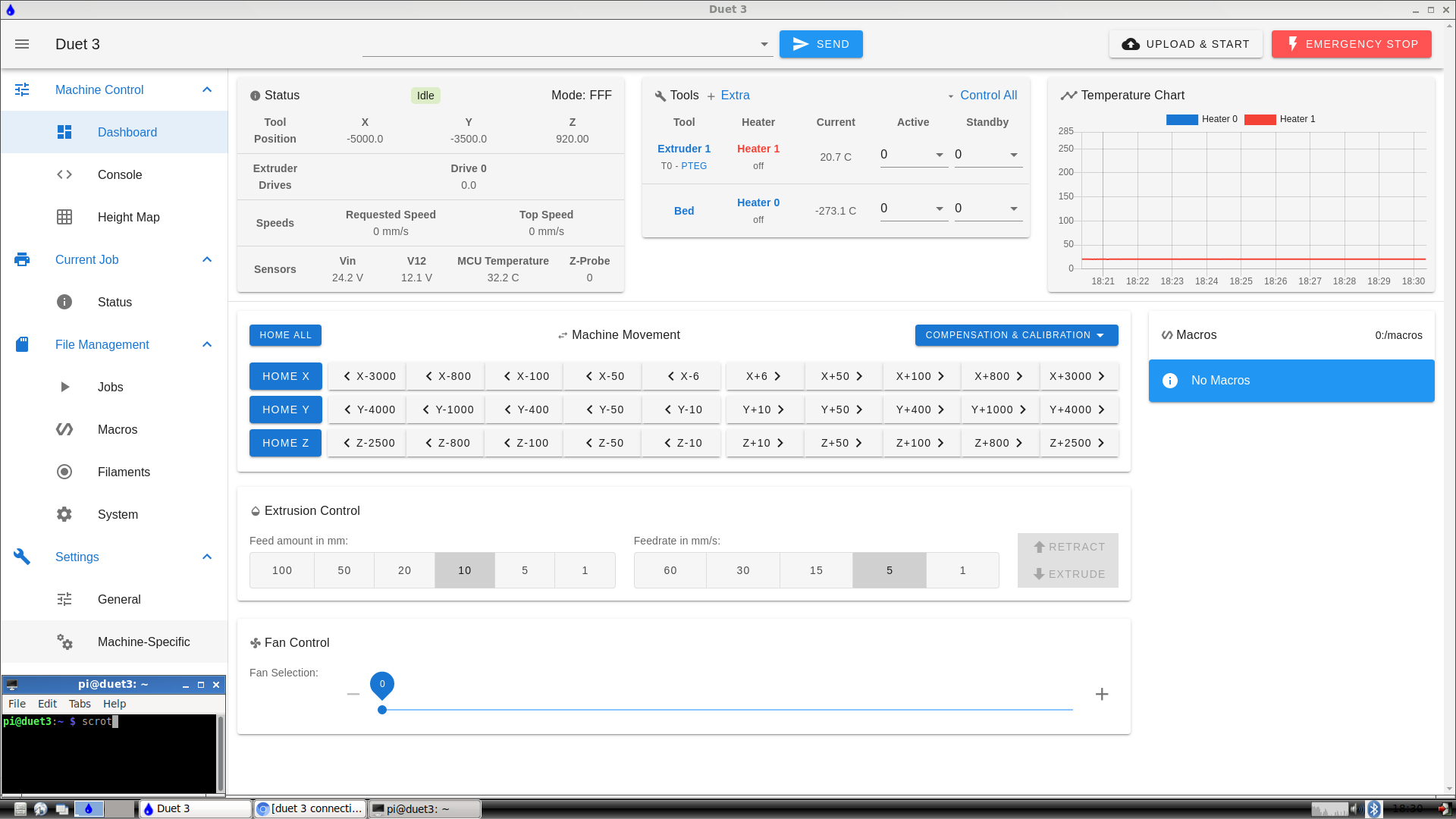
@Phaedrux ok, just removed the “^” from in front. Still nothing. Just to clarify, it’s supposed to show 0 under “z probe” when it’s not sensing and 1000 when it is, right? Not sure if it’s my code still or wiring ? I have it wired from the 3.3v to the ground and io5in.
-
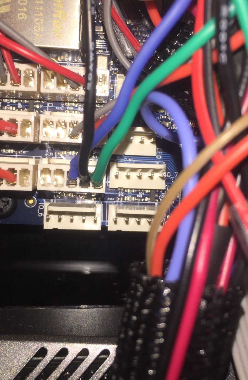
Can you post a photo of how it's wired up?
Does it have it's own indicator light showing when it's triggering? -
; Z-Probe
M558 P5 C"!io5.in" H5 F120 T6000                   ; set Z probe type to switch and the dive height + speeds
G31 P500 X41 Y41 Z2.5                              ; set Z probe trigger value, offset and trigger height
M557 X15:215 Y15:195 S20                           ; define mesh grid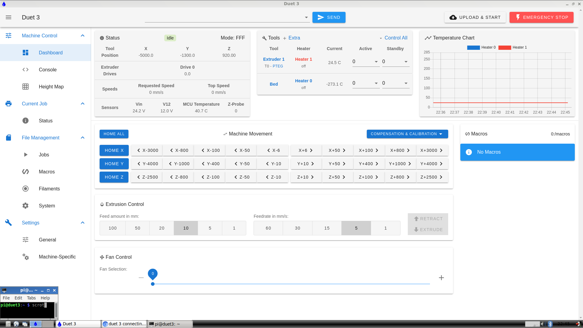
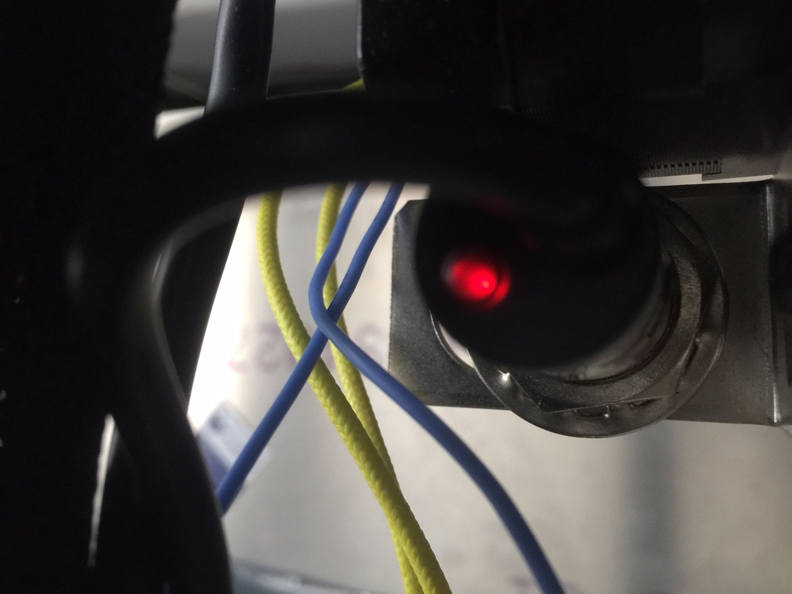
-
So, the light turns on when I put a metal object under the sensor but doesn't indicate whether its on in the RRF dashboard . The value stays at 0 under "z probe".
-
I suspect a bad signal wire from your probe.
In your photo, which wire is which?
-
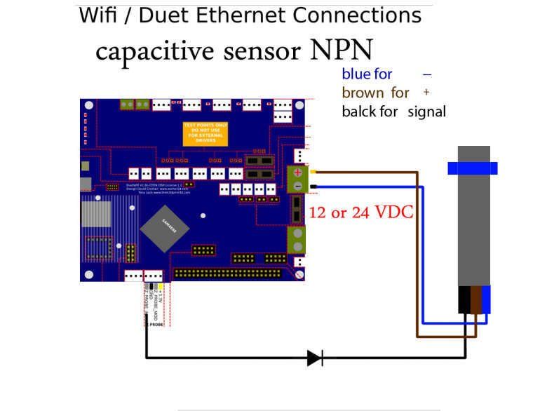
the green (actually brown) is the positive, the black is the sensor, and the blue is negative. i may be wrong. reference diagram.
-
You have the brown/green wire connected to the 3.3v for power.
The diagram shows the probe being connected to 12/24v vin.
Does your probe function at 3.3v or does it need more?
-
@Phaedrux I just connected it to vin 24v but still see no difference in the z probe value.
-
Do you have a link to information on what probe it actually is?
-
@Phaedrux This is the exact one. looks like the pnp style sensors require a resistor?