Independent Z axis Homing using BL Touch
-
@fcwilt @Thalios
So now the Z axis are being independently homed. At least they move to the locations and for z after the center bed z probe. It will then run the mesh bed calibration.However I'm still getting:
G28
Error: Some computed corrections exceed configured limit of 1.00mm: -2.040 2.318
Where is this coming from?
config:
; Configuration file for Duet WiFi (firmware version 3)
; executed by the firmware on start-up
;
; generated by RepRapFirmware Configuration Tool v3.1.4 on Mon Sep 28 2020 07:45:49 GMT-0600 (Mountain Daylight Time)

; General preferences
G90                                                ; send absolute coordinates...
M83                                                ; ...but relative extruder moves
M550 P"A.C.E."                                     ; set printer name
M918 P1 E4 F2000000                                ; configure direct-connect display

; Network
M551 P"SpaceForceHu2020!!"                         ; set password
M552 S1                                            ; enable network
M586 P0 S1                                         ; enable HTTP
M586 P1 S0                                         ; disable FTP
M586 P2 S0                                         ; disable Telnet

; Drives
M569 P0 S1                                         ; X physical drive 0 goes backwards
M569 P1 S1                                         ; Y physical drive 1 goes backwards
M569 P2 S0                                         ; Z One physical drive 2 goes forwards
M569 P3 S0                                         ; E physical drive 3 goes backwards
M569 P4 S0                                         ; Z Two physical drive 2 goes forwards
M584 X0 Y1 Z2:4 E3                                 ; set drive mapping
M350 X16 Y16 Z16 E16 I1                            ; configure microstepping with interpolation
M92 X80.00 Y80.00 Z400.00 E415.00                  ; set steps per mm
M566 X1200.00 Y1200.00 Z24.00 E300.00              ; set maximum instantaneous speed changes (mm/min)
M203 X9000.00 Y9000.00 Z180.00 E6000.00            ; set maximum speeds (mm/min)
M201 X500.00 Y500.00 Z100.00 E5000.00              ; set accelerations (mm/s^2)
M906 X800 Y1500 Z800 E1000 I50                     ; set motor currents (mA) and motor idle factor in per cent
M84 S30                                            ; Set idle timeout

; Axis Limits
;M208 X30:470 Y0:250                               ; X carriage moves from 30 to 470, Y bed goes from 0 to 250
M208 X0:500 Y0:500 Z0:500                          ; set axis minima
;M208 X500 Y500 Z500 S0                            ; set axis maxima

;Filiment Out Sensor
M591 D0 P1 C"e0stop" S1                            ; filiment out sensor


; Endstops
M574 X1 S1 P"xstop"                                ; configure active-high endstop for low end on X via pin xstop
M574 Y1 S1 P"ystop"                                ; configure active-high endstop for low end on Y via pin ystop
M574 Z1 S2                                         ; configure Z-probe endstop for low end on Z

; Z-Probe
M950 S0 C"exp.heater7"                             ; create servo pin 0 for BLTouch
M558 P9 C"^zprobe.in" H5 F600 T9000                ; set Z probe type to bltouch and the dive height + speeds
G31 P25 X37 Y0 Z2.150                              ; set Z probe trigger value, offset and trigger height
M557 X40:470 Y40:470 S25                           ; define mesh grid

; Heaters
M308 S0 P"bedtemp" Y"thermistor" T100000 B4092     ; configure sensor 0 as thermistor on pin bedtemp
M950 H0 C"bedheat" T0                              ; create bed heater output on bedheat and map it to sensor 0
M307 H0 A340.0 C140.0 D600 S1.00 B1                ; enable bang-bang mode for the bed heater and set PWM limit
M140 H0                                            ; map heated bed to heater 0
M143 H0 S72                                        ; set temperature limit for heater 0 to 72C
M308 S1 P"e0temp" Y"thermistor" T100000 B4725 C7.06e-8   ; configure sensor 1 as thermistor on pin e0temp
M950 H1 C"e0heat" T1                               ; create nozzle heater output on e0heat and map it to sensor 1
M307 H1 B0 S1.00                                   ; disable bang-bang mode for heater  and set PWM limit

; Fans
M950 F0 C"fan0" Q500                               ; create fan 0 on pin fan0 and set its frequency
M106 P0 S1 H-1                                     ; set fan 0 value. Thermostatic control is turned off
M950 F1 C"fan1" Q500                               ; create fan 1 on pin fan1 and set its frequency
M106 P1 S1 H1 T45                                  ; set fan 1 value. Thermostatic control is turned on
M950 F2 C"fan2" Q500                               ; create fan 2 on pin fan2 and set its frequency
M106 P2 S1 H1:0 T45                                ; set fan 2 value. Thermostatic control is turned on

; Tools
M563 P0 S"Hot end" H1 D0 F1:2                      ; define tool 1
G10 P0 X0 Y0 Z0                                    ; set tool 1 axis offsets
G10 P0 R0 S0                                       ; set initial tool 1 active and standby temperatures to 0C


; Custom settings are not defined

; Miscellaneous
M911 S10 R11 P"M913 X0 Y0 G91 M83 G1 Z3 E-5 F1000" ; set voltage thresholds and actions to run on power loss
bed:
; bed.g
;
M671 X-23:523 Y0:0 S1       ; Z axis lead screw locations
M561                        ; clear any bed transform
G30 P0 X40 Y250 Z-99999     ; probe near a leadscrew, half way along Y axis
G30 P1 X450 Y250 Z-99999 S2 ; probe near a leadscrew and calibrate 2 motors
G29                         ; or G29 S1 - create or load bed compensation mesh
G1 X213 Y250
G30
home all:
; homeall.g
;
M98 P"homeX.g"      ; executes home X Axis
M98 P"homeY.g"      ; executes home Y Axis
M98 P"homeZ.g"      ; executes home Z Axis
G32
G32
G32
home z:
; homez.g ; called to home the Z axis ; ; generated by RepRapFirmware Configuration Tool v3.1.4 on Mon Sep 28 2020 07:45:49 GMT-0600 (Mountain Daylight Time) G91 ; relative positioning G1 H2 Z5 F9000 ; lift Z relative to current position G90 ; absolute positioning G1 X213 Y250 F9000 ; go to first probe point G30 ; home Z by probing the bed -
As I said you need to increase the S value in your M671. You have it set at 1mm. Your G32 says you have -2.xx to +2.xx, so a total of 4.5 to 5mm difference. Make it 6mm and be done with it.
-
@Gost101 said in Independent Z axis Homing using BL Touch:
However I'm still getting:
G28
Error: Some computed corrections exceed configured limit of 1.00mm: -2.040 2.318
Where is this coming from?Increase the S value in
M671 X-23:523 Y0:0 S1to something like S5.Make sure that the Z axis motors are connected as they are defined by M584 and the leadscrew positions (M671), or the correction will go the wrong way. Currently you have:
M584 X0 Y1 Z2:4 E3
M671 X-23:523 Y0:0 S1So the motor plugged into motor driver 2 (the Z driver) should be driving the left hand side leadscrew at X-23, and the motor plugged into driver 4 (the E1 driver) should be driving the right hand side leadscrew at X523.
Ian
-
@droftarts said in Independent Z axis Homing using BL Touch:
M584
@droftarts The Z axis motor at X 523 will go down while the other goes up. How would I correct this? I did increase the S value to 5.
bed g; bed.g ; M671 X-23:523 Y0:0 S5 ; Z axis lead screw locations M561 ; clear any bed transform G30 P0 X40 Y250 Z-99999 ; probe near a leadscrew, half way along Y axis G30 P1 X450 Y250 Z-99999 S2 ; probe near a leadscrew and calibrate 2 motors G29 ; or G29 S1 - create or load bed compensation mesh G1 X213 Y250 G30config:
; Configuration file for Duet WiFi (firmware version 3) ; executed by the firmware on start-up ; ; generated by RepRapFirmware Configuration Tool v3.1.4 on Mon Sep 28 2020 07:45:49 GMT-0600 (Mountain Daylight Time) ; General preferences G90 ; send absolute coordinates... M83 ; ...but relative extruder moves M550 P"A.C.E." ; set printer name M918 P1 E4 F2000000 ; configure direct-connect display ; Network M551 P"SpaceForceHu2020!!" ; set password M552 S1 ; enable network M586 P0 S1 ; enable HTTP M586 P1 S0 ; disable FTP M586 P2 S0 ; disable Telnet ; Drives M569 P0 S1 ; X physical drive 0 goes backwards M569 P1 S1 ; Y physical drive 1 goes backwards M569 P2 S0 ; Z One physical drive 2 goes forwards M569 P3 S0 ; E physical drive 3 goes backwards M569 P4 S0 ; Z Two physical drive 2 goes forwards M584 X0 Y1 Z2:4 E3 ; set drive mapping M350 X16 Y16 Z16 E16 I1 ; configure microstepping with interpolation M92 X80.00 Y80.00 Z400.00 E415.00 ; set steps per mm M566 X1200.00 Y1200.00 Z24.00 E300.00 ; set maximum instantaneous speed changes (mm/min) M203 X9000.00 Y9000.00 Z180.00 E6000.00 ; set maximum speeds (mm/min) M201 X500.00 Y500.00 Z100.00 E5000.00 ; set accelerations (mm/s^2) M906 X800 Y1500 Z800 E1000 I50 ; set motor currents (mA) and motor idle factor in per cent M84 S30 ; Set idle timeout ; Axis Limits ;M208 X30:470 Y0:250 ; X carriage moves from 30 to 470, Y bed goes from 0 to 250 M208 X0:500 Y0:500 Z0:500 ; set axis minima ;M208 X500 Y500 Z500 S0 ; set axis maxima ;Filiment Out Sensor M591 D0 P1 C"e0stop" S1 ; filiment out sensor ; Endstops M574 X1 S1 P"xstop" ; configure active-high endstop for low end on X via pin xstop M574 Y1 S1 P"ystop" ; configure active-high endstop for low end on Y via pin ystop M574 Z1 S2 ; configure Z-probe endstop for low end on Z ; Z-Probe M950 S0 C"exp.heater7" ; create servo pin 0 for BLTouch M558 P9 C"^zprobe.in" H5 F600 T9000 ; set Z probe type to bltouch and the dive height + speeds G31 P25 X37 Y0 Z2.150 ; set Z probe trigger value, offset and trigger height M557 X40:470 Y40:470 S25 ; define mesh grid ; Heaters M308 S0 P"bedtemp" Y"thermistor" T100000 B4092 ; configure sensor 0 as thermistor on pin bedtemp M950 H0 C"bedheat" T0 ; create bed heater output on bedheat and map it to sensor 0 M307 H0 A340.0 C140.0 D600 S1.00 B1 ; enable bang-bang mode for the bed heater and set PWM limit M140 H0 ; map heated bed to heater 0 M143 H0 S72 ; set temperature limit for heater 0 to 72C M308 S1 P"e0temp" Y"thermistor" T100000 B4725 C7.06e-8 ; configure sensor 1 as thermistor on pin e0temp M950 H1 C"e0heat" T1 ; create nozzle heater output on e0heat and map it to sensor 1 M307 H1 B0 S1.00 ; disable bang-bang mode for heater and set PWM limit ; Fans M950 F0 C"fan0" Q500 ; create fan 0 on pin fan0 and set its frequency M106 P0 S1 H-1 ; set fan 0 value. Thermostatic control is turned off M950 F1 C"fan1" Q500 ; create fan 1 on pin fan1 and set its frequency M106 P1 S1 H1 T45 ; set fan 1 value. Thermostatic control is turned on M950 F2 C"fan2" Q500 ; create fan 2 on pin fan2 and set its frequency M106 P2 S1 H1:0 T45 ; set fan 2 value. Thermostatic control is turned on ; Tools M563 P0 S"Hot end" H1 D0 F1:2 ; define tool 1 G10 P0 X0 Y0 Z0 ; set tool 1 axis offsets G10 P0 R0 S0 ; set initial tool 1 active and standby temperatures to 0C ; Custom settings are not defined ; Miscellaneous M911 S10 R11 P"M913 X0 Y0 G91 M83 G1 Z3 E-5 F1000" ; set voltage thresholds and actions to run on power loss -
@Gost101 said in Independent Z axis Homing using BL Touch:
M584 X0 Y1 Z2:4 E3
Which motor is connected to driver 2 and which to driver 4?
-
@Phaedrux that would be the motor that goes down.
-
@Gost101 said in Independent Z axis Homing using BL Touch:
@Phaedrux that would be the motor that goes down.
That answer makes NO sense. We can’t see what you’re seeing, so you need to answer questions clearly, or we end up with another 100+ post thread.
If the motors are moving the wrong way during levelling ie it gets worse not better, either swap the Z motor connections, or change M584 to
M584 X0 Y1 Z4:2 E3Mapping the correct motor to the correct leadscrew is fundamental to bed levelling, and is clearly covered in the documentation. Please read and follow documentation more carefully, it’ll save you a lot of time and unnecessary questions.
Ian
-
@droftarts @Phaedrux Both z axis work fine going up and down during all other aspects of the calibration eg, home z, manually going up and down. Only when the x axis is trying to be leveled via the z axis does the motor 2 z axis move so far down that the x axis becomes uneven to the bed.
-
@Gost101 the bed levelling rotates around X0, so one side (should be the right side, at X523) will move much more than the other side. If the left side is moving a large amount, and as I’ve told you three times now, swap the Z motors connections at the Duet over!
Ian
-
@droftarts I understand now. I had a brain fart right then. It's all fixed. It works very well now. Now for some reason the height map is very weird compared to what it used to be. This is what I see. So I have to do anything to my slicer Cura to use the mesh bed?
-
@Gost101 glad you got it working. You didn’t post an image of your bed mesh, though.
Ian
-
@droftarts I fixed the height map now its working. It had a corupt file that I just had to delete. Do I have to do anything with my slicer?
-
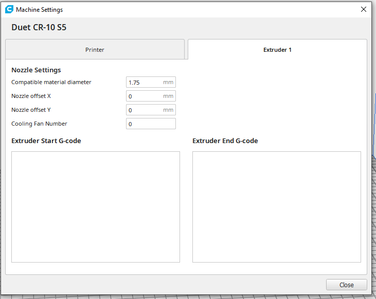
Here is my Slicer Settings:
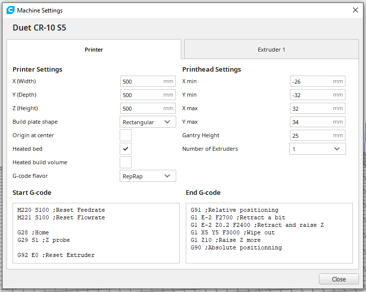
Start:M220 S100 ;Reset Feedrate M221 S100 ;Reset Flowrate G28 ;Home G29 S1 ;Z probe G92 E0 ;Reset Extruder G1 Z2.0 F3000 ;Move Z Axis up G1 X10.1 Y20 Z0.28 F5000.0 ;Move to start position G1 X10.1 Y200.0 Z0 F1500.0 E15 ;Draw the first line G1 X10.4 Y200.0 Z0.28 F5000.0 ;Move to side a little G1 X10.4 Y20 Z0 F1500.0 E30 ;Draw the second line G92 E0 ;Reset Extruder G1 Z2.0 F3000 ;Move Z Axis upEnd:
G91 ;Relative positioning G1 E-2 F2700 ;Retract a bit G1 E-2 Z0.2 F2400 ;Retract and raise Z G1 X5 Y5 F3000 ;Wipe out G1 Z10 ;Raise Z more G90 ;Absolute positionning G1 X0 Y{machine_depth} ;Present print M106 S0 ;Turn-off fan M104 S0 ;Turn-off hotend M140 S0 ;Turn-off bed M84 X Y E ;Disable all steppers but Z -
Once I'm done I will create a new thread for people in the future to look at for my printers configuration.
-
Then I will work on the ultimate printer project which will take 1 year + to finish. I appreciate all the help that you all provide @fcwilt @droftarts @Thalios @Phaedrux @dc42. Will there be an expansion board in which I could plug in my own stepper driver? Curious about testing a closed loop system.
-
Hi,
The only thing I have in my slicer is M98 P"print_begin.g" and M98 P"print_end.g".
I'm pretty sure you can figure out what kinds of commands I have in each of those files.
I use that approach so I don't have to worry about putting the same code (other than the M98s) into each slicer I happen to be using.
The firmware supports, as you seem to be aware, a start.g file.
I heard that the firmware also supports an end.f file but I couldn't get it to run.
As I recall start.g runs before anything the slicers run, including M98 calls likes mine.
Also there are often slicer settings that specify the "flavor" of gcode (like marlin, reprap, etc) used by your printer controller. That setting determines what gcode the slicer executes at the start and end of a print independent of anything that appears in the "Start G-code" and "End G-code" boxes in the slicer.
Frederick
-
@fcwilt Thanks for your help. Question though for my z probe offset height is set to 2.250 but Everytime I start a print I have to lower the z axis to -0.15. do I increase the offset hight or decrease it?
-
@Gost101 said in Independent Z axis Homing using BL Touch:
@fcwilt Thanks for your help. Question though for my z probe offset height is set to 2.250 but Everytime I start a print I have to lower the z axis to -0.15. do I increase the offset hight or decrease it?
While it may seen odd "higher = closer" - so increase the trigger height it by 0.15 and see how it works.
Frederick
-
This post is deleted!