Duet3D Logo

    Duet3D

    • Register
    • Login
    • Search
    • Categories
    • Tags
    • Documentation
    • Order

    How to use a LED Strip with Duet 2 WiFI?

    Duet Hardware and wiring
    6
    30
    2283
    Loading More Posts
    • Oldest to Newest
    • Newest to Oldest
    • Most Votes
    Reply
    • Reply as topic
    Log in to reply
    This topic has been deleted. Only users with topic management privileges can see it.
    • A Former User
      A Former User last edited by A Former User

      Good morning, I've seen that it is possible to "add" a LED stripe to a Duet and control it for lighting during the print. Can someone suggest me what model of strip I could use? I already own an Adafruit RGBW wich I used with Marlin, can I use it as well?....have an ATX power supply and the 5VDC line is "free" so I can use it for the stripe. After that what GCODE should I insert in the start and end gocdes to turn it on an off? Should I use M150 [B<intensity>] [P<intensity>] [R<intensity>] [U<intensity>] [W<intensity>] like with Marlin?

      Thanks

      1 Reply Last reply Reply Quote 0
      • Veti
        Veti last edited by

        there is an example on how to use neoplixel with the blv cube

        https://www.blvprojects.com/blv-mgn-cube-3d-printer

        A Former User 1 Reply Last reply Reply Quote 0
        • A Former User
          A Former User @Veti last edited by

          @Veti said in How to use a LED Strip with Duet 2 WiFI?:

          there is an example on how to use neoplixel with the blv cube

          https://www.blvprojects.com/blv-mgn-cube-3d-printer

          mmmhh....the neopixel rings are driven by an Arduino...I want a much easier way to control a strip...maybe I could "give up" the RGBW and buy a simple white strip, for me it is important to be able to automatically turn it on and off during the print....

          dc42 1 Reply Last reply Reply Quote 0
          • dc42
            dc42 administrators @Guest last edited by

            @the_dragonlord said in How to use a LED Strip with Duet 2 WiFI?:

            maybe I could "give up" the RGBW and buy a simple white strip, for me it is important to be able to automatically turn it on and off during the print....

            You can run a 12V or 24V (depending on your VIN) LED strip from a spare fan or heater output on the Duet.

            It would be possible to add DotStar LED strip support to the firmware for Duet WiFi/Ethernet/Maestro, but you would need to use a gate/level-shifter to convert the 3.3v SPI signals to 5V and gate the SPI clock with CS. Essentially the same circuit as needed to connect a 12864 LCD to a Duet 2. You would need to provide separate 5V power to the DotStar strip because they draw a lot of current.

            Neopixel LEDs need a dedicated or semi-dedicated SPI channel, so are more difficult to drive.

            Duet WiFi hardware designer and firmware engineer
            Please do not ask me for Duet support via PM or email, use the forum
            http://www.escher3d.com, https://miscsolutions.wordpress.com

            A Former User 1 Reply Last reply Reply Quote 0
            • A Former User
              A Former User @dc42 last edited by

              @dc42 for me at now is enough to be able to drive via gcode a mosfet wich drives a simple led stripe, it would be great to be able to set the brightness too... maybe it is possible moduling the pwm? In case how can I use a pin via gcode?

              dc42 1 Reply Last reply Reply Quote 0
              • dc42
                dc42 administrators @Guest last edited by

                @the_dragonlord said in How to use a LED Strip with Duet 2 WiFI?:

                @dc42 for me at now is enough to be able to drive via gcode a mosfet wich drives a simple led stripe, it would be great to be able to set the brightness too... maybe it is possible moduling the pwm? In case how can I use a pin via gcode?

                Yes you can use PWM. See https://duet3d.dozuki.com/Wiki/Using_servos_and_controlling_unused_IO_pins (note, this has not yet been updated to cover RepRapFirmware 3).

                Duet WiFi hardware designer and firmware engineer
                Please do not ask me for Duet support via PM or email, use the forum
                http://www.escher3d.com, https://miscsolutions.wordpress.com

                A Former User 2 Replies Last reply Reply Quote 0
                • A Former User
                  A Former User @dc42 last edited by

                  @dc42 wow so i could use a servo pin to drive a mosfet in pwm like this and so be able to start and stop the lighting with the print and adjust the brightness as well!

                  dc42 1 Reply Last reply Reply Quote 0
                  • dc42
                    dc42 administrators @Guest last edited by

                    @the_dragonlord said in How to use a LED Strip with Duet 2 WiFI?:

                    @dc42 wow so i could use a servo pin to drive a mosfet in pwm like this and so be able to start and stop the lighting with the print and adjust the brightness as well!

                    Yes.

                    Duet WiFi hardware designer and firmware engineer
                    Please do not ask me for Duet support via PM or email, use the forum
                    http://www.escher3d.com, https://miscsolutions.wordpress.com

                    A Former User 1 Reply Last reply Reply Quote 0
                    • A Former User
                      A Former User @dc42 last edited by

                      @dc42 excellent my friend, thank you soooooo much!

                      1 Reply Last reply Reply Quote 0
                      • A Former User
                        A Former User @dc42 last edited by

                        @dc42 I'm trying to configure it, I used the commands:

                        M950 S0 C"exp.heater4" to map the heater4 pin for the servo indexed 0,

                        I've attached the GND and the exp.heater pins to a command port of a Mosfet but if I lunch the command

                        M280 P0 S100000

                        To try to give a 100000 micro second (a second) pulse just to try nothing happens and the Mosfet doesn't trigger....so I'm afraid that the Mosfet doesn't trigger with the high value given by the remapped heater4....I need a 12V PWM output to trigger the mosfet, I think I could use a PWM fan, could I? Honestly I've tried to read the documentation for how to comand a PWM fan via gcode but I didn't understand so much....I've found this example:

                        M950 F2 C"!Fan2+exp.pb6" Q25000 ; fan 2 is a 4-wire PWM fan so invert it, use high PWM frequency, tacho connected to PB6 on expansion connector

                        But I can't understand because looking at the wiring diagram FAN2 isn't a 4 pin Cattura.JPG
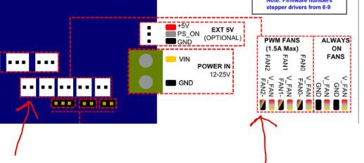
                        And I don't understand why I had to use an expansion pin too....so as you can see I'm a looooooooooooooot confusing and I'd better not to go with "trial & error" because I don't want to burn the board....the main question is: can I use the FAN2 2 pins to trigger the mosfet with 12vdc and start, modulate the PWM, and stop the FAN (led stripe) via gcode? In case how?
                        Thanks a lot!

                        1 Reply Last reply Reply Quote 0
                        • Phaedrux
                          Phaedrux Moderator last edited by

                          I think you're overthinking it. The fan ports use PWM by switching the negative side and don't require the 4 pin that a true 4 wire PWM fan does (though that is an option, it's not what you need for a simple LED strip).

                          Just connect your LED string to Fan2 and control it like a regular part cooling fan.

                          M950 F2 C"Fan2" Q500
                          M106 P2 S255

                          Z-Bot CoreXY Build | Thingiverse Profile

                          A Former User 1 Reply Last reply Reply Quote 0
                          • A Former User
                            A Former User @Phaedrux last edited by

                            @Phaedrux said in How to use a LED Strip with Duet 2 WiFI?:

                            I think you're overthinking it. The fan ports use PWM by switching the negative side and don't require the 4 pin that a true 4 wire PWM fan does (though that is an option, it's not what you need for a simple LED strip).

                            Just connect your LED string to Fan2 and control it like a regular part cooling fan.

                            M950 F2 C"Fan2" Q500
                            M106 P2 S255

                            thanks soooooo much

                            1 Reply Last reply Reply Quote 0
                            • ericlmccormick
                              ericlmccormick last edited by

                              I have a 24v psu so I use a 24v led strip. I first used a fan output, however the voltage drop caused an issue with my other fans. I switch to using heater output 2 and it works flawlessly.

                              ericlmccormick 1 Reply Last reply Reply Quote 0
                              • ericlmccormick
                                ericlmccormick @ericlmccormick last edited by

                                In config. g
                                ;LED Strip
                                M950 P2 C"e1heat"
                                M307 P2 A-1 C-1 D-1

                                Then add the following to change power output
                                M42 P2 Sxxx

                                Phaedrux A Former User 2 Replies Last reply Reply Quote 0
                                • Phaedrux
                                  Phaedrux Moderator @ericlmccormick last edited by

                                  @ericlmccormick said in How to use a LED Strip with Duet 2 WiFI?:

                                  M307 P2 A-1 C-1 D-1

                                  No longer used in RRF3.

                                  Z-Bot CoreXY Build | Thingiverse Profile

                                  Chriss 1 Reply Last reply Reply Quote 0
                                  • Chriss
                                    Chriss @Phaedrux last edited by

                                    @Phaedrux

                                    I have a question here too. 🙂

                                    I use that code to configure my LED strip:

                                    M950 F3 C"0.out6" Q500
                                    M106 P3 S0
                                    

                                    (And I have two macros to turn in on and off via the web or display than.)

                                    So the "controller" is called "Fan 3" on the Display. Is there a way to rename the object? Like I can rename a tool? (563 S"BlaBla")

                                    Cheers, Chriss

                                    Phaedrux 1 Reply Last reply Reply Quote 0
                                    • Phaedrux
                                      Phaedrux Moderator @Chriss last edited by

                                      @Chriss Yes, M106 C"LEDs" would give it the name LEDs.

                                      https://duet3d.dozuki.com/Wiki/Gcode#Section_M106_Fan_On

                                      Z-Bot CoreXY Build | Thingiverse Profile

                                      Chriss 1 Reply Last reply Reply Quote 0
                                      • Chriss
                                        Chriss @Phaedrux last edited by

                                        @Phaedrux

                                        Thanks! Workes as expected. 🙂 I expected that in the "M950" because that is the configuration of the object to me and "M106" the "on/off" only. So I did not looked into the docu of M106.
                                        Anyway: Thank you very much for the fast answer.

                                        Cheers, Chriss

                                        1 Reply Last reply Reply Quote 0
                                        • A Former User
                                          A Former User @ericlmccormick last edited by

                                          @ericlmccormick said in How to use a LED Strip with Duet 2 WiFI?:

                                          In config. g
                                          ;LED Strip
                                          M950 P2 C"e1heat"
                                          M307 P2 A-1 C-1 D-1

                                          Then add the following to change power output
                                          M42 P2 Sxxx

                                          Done! When I boot the board the pin is setted "high" and the LED stripe is immediately turned on with the maximum pulse width. How can I set to let the pin low when the board starts?

                                          1 Reply Last reply Reply Quote 0
                                          • ericlmccormick
                                            ericlmccormick last edited by

                                            Make sure the M42 code is in the slicer startup code and NOT in config.g

                                            I put M32 in my slicer start code which calls beg.g and M0 in my slicer end code which runs stop.g

                                            Then I have M42 P2 S255 in my bed.g and M42 P2 S0 in stop.g and cancel.g

                                            A Former User 1 Reply Last reply Reply Quote 0
                                            • A Former User
                                              A Former User @ericlmccormick last edited by

                                              @ericlmccormick said in How to use a LED Strip with Duet 2 WiFI?:

                                              Make sure the M42 code is in the slicer startup code and NOT in config.g

                                              I put M32 in my slicer start code which calls beg.g and M0 in my slicer end code which runs stop.g

                                              Then I have M42 P2 S255 in my bed.g and M42 P2 S0 in stop.g and cancel.g

                                              already done but the stripe turns on when I boot the board even without m42

                                              ericlmccormick 1 Reply Last reply Reply Quote 0
                                              • ericlmccormick
                                                ericlmccormick @Guest last edited by

                                                @the_dragonlord can you share your config.g file?

                                                A Former User 1 Reply Last reply Reply Quote 0
                                                • A Former User
                                                  A Former User @ericlmccormick last edited by A Former User

                                                  @ericlmccormick said in How to use a LED Strip with Duet 2 WiFI?:

                                                  @the_dragonlord can you share your config.g file?

                                                  here it is:

                                                  ; Configuration file for Duet WiFi (firmware version 3)
                                                  ; executed by the firmware on start-up
                                                  ;
                                                  ; generated by RepRapFirmware Configuration Tool v3.1.4 on Mon Oct 26 2020 18:43:35 GMT+0100 (Ora standard dell’Europa centrale)

                                                  ; General preferences
                                                  G90 ; send absolute coordinates...
                                                  M83 ; ...but relative extruder moves
                                                  M550 P"DragonCore" ; set printer name
                                                  M669 K1 ; select CoreXY mode

                                                  ; Network
                                                  M552 S1 ; enable network
                                                  M586 P0 S1 ; enable HTTP
                                                  M586 P1 S1 ; enable FTP
                                                  M586 P2 S1 ; enable Telnet

                                                  ; Drives
                                                  M569 P0 S0 ; physical drive 0 goes backwards
                                                  M569 P1 S0 ; physical drive 1 goes backwards
                                                  M569 P2 S0 ; physical drive 2 goes backwards
                                                  M569 P3 S0 ; physical drive 3 goes backwards
                                                  M584 X0 Y1 Z2 E3 ; set drive mapping
                                                  M350 X16 Y16 Z16 E16 I1 ; configure microstepping with interpolation
                                                  M92 X160.00 Y160.00 Z1200.00 E420.00 ; set steps per mm
                                                  M566 X900.00 Y900.00 Z12.00 E120.00 ; set maximum instantaneous speed changes (mm/min)
                                                  M203 X6000.00 Y6000.00 Z180.00 E1200.00 ; set maximum speeds (mm/min)
                                                  M201 X500.00 Y500.00 Z20.00 E250.00 ; set accelerations (mm/s^2)
                                                  M906 X800 Y800 Z800 E800 I30 ; set motor currents (mA) and motor idle factor in per cent
                                                  M84 S30 ; Set idle timeout

                                                  ; Axis Limits
                                                  M208 X0 Y0 Z0 S1 ; set axis minima
                                                  M208 X330 Y330 Z400 S0 ; set axis maxima

                                                  ; Endstops
                                                  M574 X1 S1 P"xstop" ; configure active-high endstop for low end on X via pin xstop
                                                  M574 Y1 S1 P"ystop" ; configure active-high endstop for low end on Y via pin ystop
                                                  M574 Z1 S2 ; configure Z-probe endstop for low end on Z

                                                  ; Z-Probe
                                                  M950 S0 C"exp.heater3" ; create servo pin 0 for BLTouch
                                                  M558 P9 C"^zprobe.in" H5 F120 T6000 ; set Z probe type to bltouch and the dive height + speeds
                                                  G31 P500 X0 Y0 Z0.474 ; set Z probe trigger value, offset and trigger height
                                                  M557 X15:315 Y15:315 S20 ; define mesh grid

                                                  ; Heaters
                                                  M308 S0 P"bedtemp" Y"thermistor" T100000 B4092 ; configure sensor 0 as thermistor on pin bedtemp
                                                  M950 H0 C"bedheat" T0 ; create bed heater output on bedheat and map it to sensor 0
                                                  M307 H0 B0 S1.00 ; disable bang-bang mode for the bed heater and set PWM limit
                                                  M140 H0 ; map heated bed to heater 0
                                                  M143 H0 S120 ; set temperature limit for heater 0 to 120C
                                                  M308 S1 P"e0temp" Y"thermistor" T100000 B4725 C7.06e-8 ; configure sensor 1 as thermistor on pin e0temp
                                                  M950 H1 C"e0heat" T1 ; create nozzle heater output on e0heat and map it to sensor 1
                                                  M307 H1 B0 S1.00 ; disable bang-bang mode for heater and set PWM limit

                                                  ; Fans
                                                  M950 F0 C"fan0" Q500 ; create fan 0 on pin fan0 and set its frequency
                                                  M106 P0 S0 H-1 ; set fan 0 value. Thermostatic control is turned off
                                                  M950 F1 C"fan1" Q500 ; create fan 1 on pin fan1 and set its frequency
                                                  M106 P1 S1 H1 T50 ; set fan 1 value. Thermostatic control is turned on
                                                  M950 F2 C"fan2" Q500 ; create fan 2 on pin fan2 and set its frequency
                                                  M106 P2 S1 H-1 ; set fan 2 value. Thermostatic control is turned off

                                                  ; Tools
                                                  M563 P0 S"E3DVolcano" D0 H1 F0 ; define tool 0
                                                  G10 P0 X0 Y0 Z0 ; set tool 0 axis offsets
                                                  G10 P0 R0 S0 ; set initial tool 0 active and standby temperatures to 0C

                                                  ; Custom settings are not defined

                                                  ; Miscellaneous
                                                  M575 P1 S1 B57600 ; enable support for PanelDue

                                                  M501

                                                  uh, I forgot to say that I'm using a PWM fan not an heater.....sorry....

                                                  Phaedrux ericlmccormick 3 Replies Last reply Reply Quote 0
                                                  • Phaedrux
                                                    Phaedrux Moderator @Guest last edited by

                                                    @the_dragonlord said in How to use a LED Strip with Duet 2 WiFI?:

                                                    uh, I forgot to say that I'm using a PWM fan not an heater.....sorry....

                                                    Which fan header and where is the gcode defining the pin?

                                                    Z-Bot CoreXY Build | Thingiverse Profile

                                                    1 Reply Last reply Reply Quote 0
                                                    • ericlmccormick
                                                      ericlmccormick @Guest last edited by ericlmccormick

                                                      @the_dragonlord your problem is you have m106 P2 S1 H-1 and you should have m106 P2 S0 H-1

                                                      A Former User 1 Reply Last reply Reply Quote 1
                                                      • First post
                                                        Last post
                                                      Unless otherwise noted, all forum content is licensed under CC-BY-SA