First Layer and Extrusion Problems
-
@CaLviNx Thank you, then i think is everything ready. i startet to print a fanchroud out of ABS. im very curious how it comes out.
what would i have to change in my config.g to use a capazitive sensor with 3 wires ?
is the connection on the duet 3 like: +5V, GND, and io.in ?
what musst be changed in these lines ?
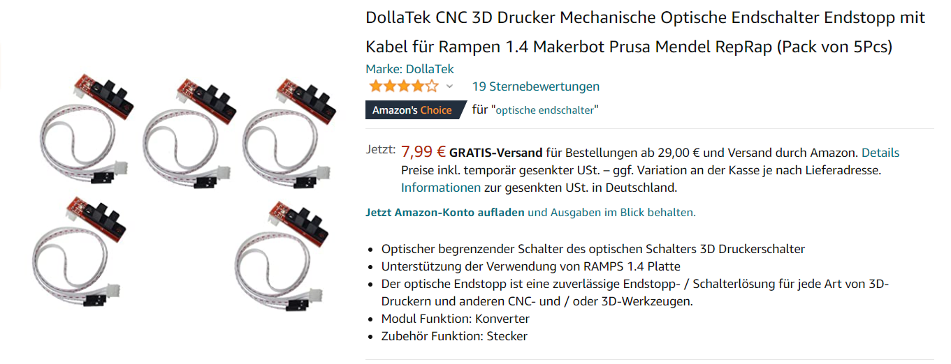
; Z-Probe
M950 S0 C"io7.out"                                    ; create servo pin 0 for BLTouch
M558 P9 C"^io7.in" H5 F120 T6000                      ; set Z probe type to bltouch and the dive height + speeds
G31 P500 X0 Y0 Z1.8                                 ; set Z probe trigger value, offset and trigger height
the last point , i want to change my mechanical endstop switches to optical ones.
But what i am doing, the endstopps are lighting up but i cant get them to trigger.i´ve got 2 different ones.
one with high level when no trigger
and one with low level when no trigger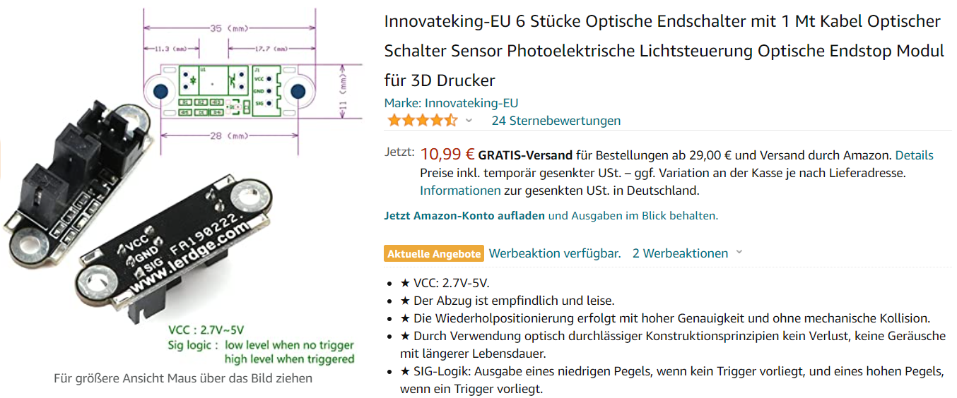
but i cant get the mo work
-
Im sorry i only used that type of Z sensor when i first started with the duet years ago, I found them to be very unreliable, they were very susceptible to temp changes , so I have forgotten how I wired them up. I only use the Duet IR sensor now
It would appear they would be as you say VCC, GND, SIG which would correspond with what you wrote.
there is a section in the Dozuki on Z-Probes
As for the optical end stops again I dont use them, I only use Omron mechanical switches, they operate fine even at high temps in a chamber.
You might try inverting the signal on either of those two switches to see if that gets them working, or another thing is to check to see what triggers them, i dont know they might be looking for a metal or a dark colour to trigger them if they are an optical IR sensor
-
@CaLviNx how do you like the mini ir sensor ? is it working better than the bltouch ?
-
@Frederik said in First Layer and Extrusion Problems:
@CaLviNx how do you like the mini ir sensor ? is it working better than the bltouch ?
Well that's a touchy subject for me at the moment....
I have 8 operational printers (and 1 core-xy in the build stage) at home, 6 of those that are running have Duet-3 's (with LC-1 tool-boards) 2 have Duet-2 wifi's installed.
All have IR Sensors fitted. The Duet-2 machines are still running RRF-2 as they just run and run and print day in day out without issue and have ran for years and years without issue.
The Duet-3 boards (all with LC1 Tool-boards) all suffer from an intermittent issue of the IR sensor triggering too soon (as in triggering when the head is about 20mm from the bed surface) doesnt happen all the time, you can boot and home and they home fine to the correct height. then you can go to home and the sensor triggers at 20mm again, I can overcome it by issuing a G92 Z30 command and manually driving the bed up very close to the head then homing Z again and this time it reads and prints correctly.(it is not the print surface as this happens on a few differing surfaces and if it was the print surface it wouldn't explain why it only happens intermittently)
As of the other day i updated my boards (and tool boards) to the newest firmware and the issue seems to be gone but we will see.
On the Duet-2's with older firmware, NO issues ever.
And as much as I personally dont like the Bl-Touch (I dont like moving parts of the pin which can get bent, and I dont like the packaging issues in mounting it), I do have a genuine one here, I did test it when I started getting early trigger issues on the IR sensor and it worked fine.
-
@Frederik said in First Layer and Extrusion Problems:
what would i have to change in my config.g to use a capazitive sensor with 3 wires ?
see
https://duet3d.dozuki.com/Wiki/Connecting_a_Z_probe#Section_NPN_output_normally_open_inductive_or_capacitive_sensor
or
https://duet3d.dozuki.com/Wiki/Connecting_a_Z_probe#Section_PNP_output_normally_open_inductive_or_capacitive_sensor -
@Veti Thank you.
Do you have an idea why I can't get optical switches to work? the LED on the sensor work and trigger, but the duet doesn't recognize it
-
@CaLviNx WOW, 8 operationl Printers ? Thats amazing. Do you make a living out of printing ?
Ok, good to know, i was thinking about getting one for testing purposes.
-
@Frederik said in First Layer and Extrusion Problems:
Do you have an idea why I can't get optical switches to work? the LED on the sensor work and trigger, but the duet doesn't recognize it
maybe you switched signal and ground. how did you connect it. the lerdge endstop work fine in my delta.
btw only black objects will really block the light. -
-
the lerdge endstops are meant for 3.3v but should also work in 5v mode
post the changes you did in the config
-
@Veti i used this config:
M574 X2 S1 P"!io1.in"                                 ; configure active-high endstop for high end on X via pin !io1.in
M574 Y1 S1 P"!io0.in"                                 ; configure active-high endstop for low end on Y via pin !io0.in
Should i connect with the additional resistors like it is mentioned in the dozuki
3.3V-compatible optical endstop Connect Gnd to Gnd, Vcc of the opto sensor to 3V3, and the output of the opto sensor to STP/IN. Opto sensors usually have active high outputs, so use S1 in the M574 command. Note: opto endstops made to the Generation 7 design are often claimed to be 3.3V-compatible, but in fact the design is marginal with a 5V supply and frequently doesn't work at all on 3.3V. Here are some workarounds: - This design normally works with a 3.3V supply if you replace the 180 ohm opto switch series resistor resistor by 100 ohms. Tip: if your opto endswitch uses surface mount resistors, instead of removing the 180 ohm resistor it is easier to solder a 200 or 220 ohm resistor on top of it, so that the two resistors are connected in parallel. Make sure you pick the correct resistor to replace or solder another on top of! There is often also a load resistor, value 1K or higher. - If you are using Duet 3 then you can use the 5V pin on the IO_ connector to provide power to the opto endstop instead of using 3.3V power. - If you are using a Duet WiFi/Ethernet hardware rev 1.04 or later or a Duet Maestro, these boards can tolerate 5V on the endstop inputs. So you can provide them with a 5V supply instead (leaving the centre pin of the endstop connector not connected) and connect the outputs of your endstops directly to the STP/IN pins of the endstop connectors. -
i run the endstops fine on my delta without resistors. the lerdge endstops are actually designed for 3.3v because the lerdge board run on 3.3v
check with m119 if you can trigger them.
-
-
maybe a bad crimp in the cable?
-
@Veti the led on the switch is on , but it doesent trigger
-
@Frederik
it could be a bad crimp in the signal wire -
@Frederik
the advantage of the lerdge endstops is they light up when they are triggered. the ramps endstops light up when they are not -
@Veti one moment , i will check it a second time
-
@Veti you were right
") I tested it with the original cable and it triggers .....yeah...thank you
I tested it with the original cable and it triggers .....yeah...thank younow both the ramps and lerdge are functioning
-
This post is deleted!