RRF3.2Beta4.1 Heightmap vs. Spindle/Driver Mapping
-
@Frederik said in RRF3.2Beta4.1 Heightmap vs. Spindle/Driver Mapping:
And after startup only a g32 - 3 point level +loading of Heightmap.csv (bed.g)
generate a Heightmap
If you can do a 3point calibration the a deviation of 0 or as close as you can get it you should not have to generate a new Heightmap every time you do a 3point calibration.
The time to temp all depends on your setup.
I have a 750w heater that covers the entire 300mm bed with a temp sensor to control the heat in a slot cutout of the magnet for the flex sheet so very close to the top of the bed. I also have a temp sensor on the heater pad itself so once they both stabilize its good to go. If you are only measuring temp at the heater pad it will take a while for the top of the bed to reach an even temp unless the bed is very thin.
@Frederik said in RRF3.2Beta4.1 Heightmap vs. Spindle/Driver Mapping:
Changed bltouch config to H3 F60 T6000 A10 B1 R0.5
What was the max Z speed for this test? The last 4 readings look good. Too high of a Z speed can cause the shift between the second and third reading.
-
@3dML Z Probing speed F60 normal in the RRF config tool was F120
-
@Frederik said in RRF3.2Beta4.1 Heightmap vs. Spindle/Driver Mapping:
@3dML Z Probing speed F60 normal in the RRF config tool was F120
Yes that is used for Z- speed when probing but M203 sets the max speed which is used for Z+. Too high of max speed will cause higher deviations when probing but not enough to notice when printing.
I have found that slowing down the maximum Z speed can help with tolerance. Try adding a M203 Z100 before any bed probing moves and M203 Z1000 after the bed probing is finished to restore the speed back to your config settings. You may be able to push the speed a little higher Z100.
-
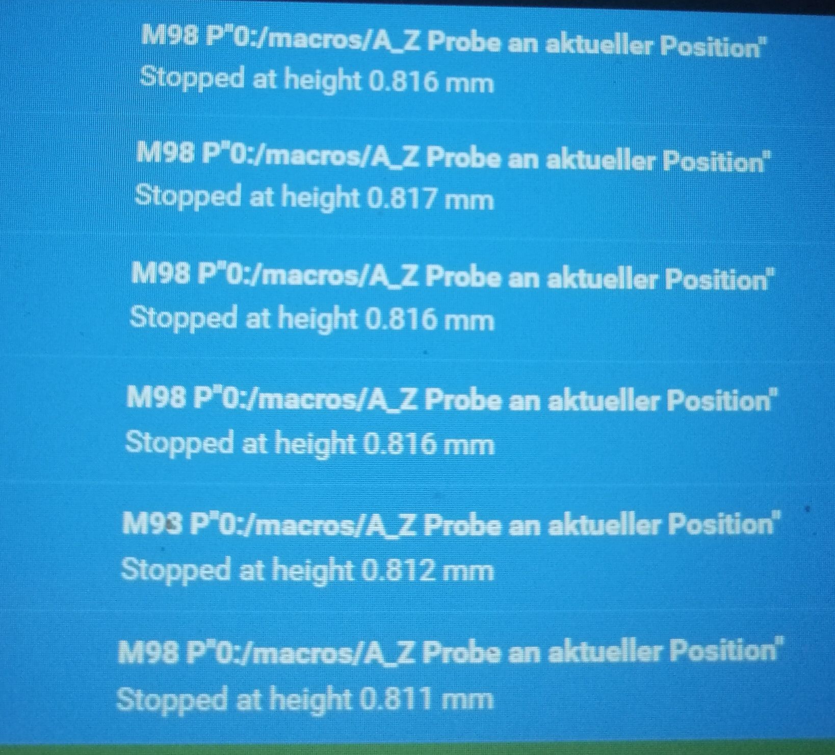
@3dML its probing with 1mm/s. is that slow enough ?
The Last G32 after changing the settings
Leadscrew adjustments made: 0.380 0.168 0.089, points used 3, (mean, deviation) before (0.244, 0.085) after (0.000, 0.000)
Leadscrew adjustments made: 0.064 -0.009 -0.213, points used 3, (mean, deviation) before (-0.044, 0.083) after (0.000, 0.000)

Leadscrew adjustments made: 0.215 0.207 -0.272, points used 3, (mean, deviation) before (0.044, 0.169) after (0.000, 0.000)
Leadscrew adjustments made: 0.011 0.098 -0.100, points used 3, (mean, deviation) before (-0.013, 0.066) after (0.000, 0.000)

Leadscrew adjustments made: -0.087 0.158 0.672, points used 3, (mean, deviation) before (0.216, 0.222) after (-0.000, 0.000)
Leadscrew adjustments made: -0.018 -0.124 0.255, points used 3, (mean, deviation) before (0.060, 0.126) after (-0.000, 0.000)

Leadscrew adjustments made: 0.305 0.199 0.353, points used 3, (mean, deviation) before (0.304, 0.054) after (-0.000, 0.000)
Leadscrew adjustments made: 0.017 -0.064 0.012, points used 3, (mean, deviation) before (0.002, 0.031) after (0.000, 0.000)

Leadscrew adjustments made: 0.278 0.250 0.293, points used 3, (mean, deviation) before (0.279, 0.015) after (0.000, 0.000)
Leadscrew adjustments made: 0.012 -0.013 -0.004, points used 3, (mean, deviation) before (0.003, 0.008) after (0.000, 0.000)

Leadscrew adjustments made: 0.264 0.270 0.289, points used 3, (mean, deviation) before (0.274, 0.008) after (0.000, 0.000)
Leadscrew adjustments made: 0.011 -0.011 -0.009, points used 3, (mean, deviation) before (0.000, 0.007) after (0.000, 0.000)
G29 81 points probed, min error -0.806, max error 0.757, mean -0.124, deviation 0.338 Height map saved to file heightmap.csvxmin,xmax,ymin,ymax,radius,xspacing,yspacing,xnum,ynum 50.00,400.00,50.00,390.00,-1.00,38.90,37.80,9,9 -0.028, -0.333, -0.536, -0.719, -0.794, -0.806, -0.694, -0.498, -0.213 0.086, -0.210, -0.423, -0.591, -0.686, -0.655, -0.535, -0.386, -0.109 0.123, -0.133, -0.348, -0.498, -0.593, -0.561, -0.411, -0.277, -0.096 0.277, -0.020, -0.213, -0.400, -0.465, -0.453, -0.370, -0.169, 0.052 0.300, 0.019, -0.156, -0.299, -0.374, -0.309, -0.263, -0.114, 0.103 0.395, 0.137, -0.045, -0.197, -0.278, -0.281, -0.146, -0.010, 0.215 0.523, 0.232, 0.018, -0.110, -0.236, -0.192, -0.128, 0.062, 0.233 0.651, 0.365, 0.130, -0.022, -0.146, -0.135, -0.048, 0.122, 0.346 0.757, 0.547, 0.280, 0.062, -0.042, -0.017, 0.075, 0.206, 0.420RepRapFirmware height map file v2 generated at 2020-12-23 01:13 xmin,xmax,ymin,ymax,radius,xspacing,yspacing,xnum,ynum 45.00,410.00,40.00,390.00,-1.00,365.00,350.00,2,2 0.423, 0.344 1.333, 1.363th last is a heightmap on the 4 corners as far out as possible
-
@Frederik
Yes if multipleG30 S-1in the same spot return a very small variation these results mean the config is not correct.If this is your only G31 this may be your problem. I just notice you have no X or Y offset for your BLTouch.
G31 P1000 X0 Y0 Z0.81 -
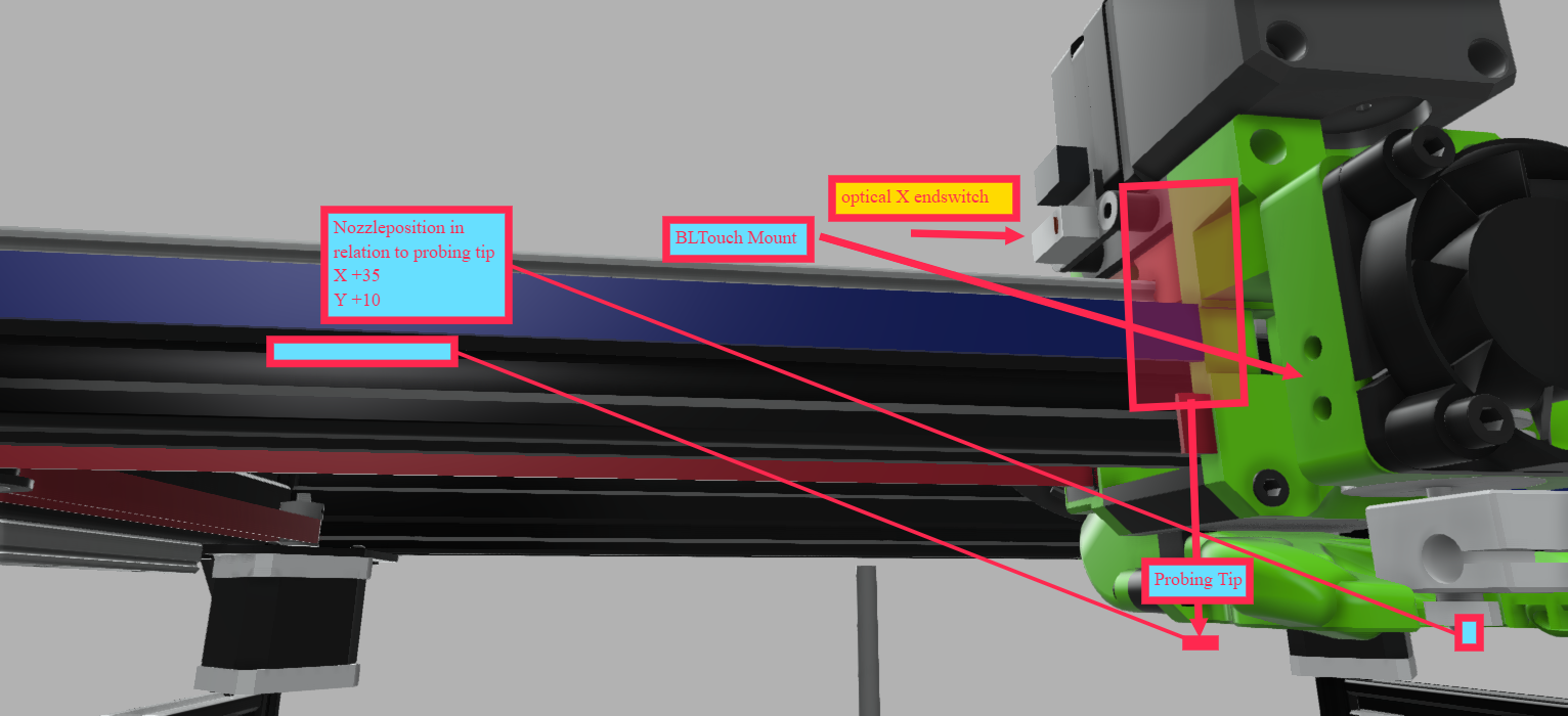
@3dML is the offset measured from the nozzle or always from x0 y0 ?
-
@Frederik
G31 is the probe offset from the nozzle. If you position the nozzle at x0 y0 the G31 offset would be the position of the BLTouch. -
@3dML when my printhead is homed at x0 y0 (left front corner) the bltouch is around x-3 y-2
the nozzle x35 y8this is are the values for another test with 4:4 Probing Points
xmin,xmax,ymin,ymax,radius,xspacing,yspacing,xnum,ynum
45.00,410.00,40.00,390.00,-1.00,121.67,116.67,4,4
  0.020, -0.735, -0.706, -0.097
  0.252, -0.427, -0.378,  0.354
  0.536, -0.148, -0.128,  0.676
  0.903,  0.127,  0.082,  0.945
-
@Frederik said in RRF3.2Beta4.1 Heightmap vs. Spindle/Driver Mapping:
@3dML when my printhead is homed at x0 y0 (left front corner) the bltouch is around x-3 y-2
the nozzle x35 y8Post the files you use for homing. The DWC tool position should report the exact position of the nozzle.
-
@Phaedrux said in RRF3.2Beta4.1 Heightmap vs. Spindle/Driver Mapping:
M671 defines the position of the lead screws
The order must match the order of the motors defined in M584
In bed.g you probe as close to the lead screws as you can in the same order as the lead screws are defined.Have you verified these settings are correct and the motors are positioned in the same order in the M671 as in the M584?
-
I added your if loop to a makro. Works almost perfekt.
Would it be possible that the measured values are displayed as message or in the console after each move? I stopped the makro after around 10min without knowing if the values are decreasing or what's happening")
I checked the limits bevor and it's running.
I also tested several mesh sizes, the resulting height maps are above.
I think, these values are reasonable to some point, I sliced a X from center of the bed 350mm to the 4 corners with a 50x50 rectangular pattern 150mm from the center.
I increased the z trigger height to 1.81mm for safety and started a really slow test pattern. Today after Work I will verify it with a good old magnetic base + digital indicator on different spots along the gantry + x and y along he bed corners. Perhaps I can shim it, modifie the mounts or something else
-
@Phaedrux
@3dML
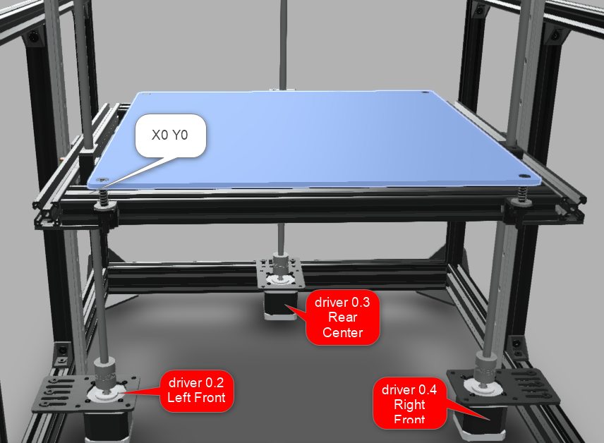
left spindle is connected to 0.2
back center to 0.3
front right to 0.4the wiring from the specified drivers to the spindles is correct
i map the Z steppers: Z02:03:04 - that should be okmy homeall.g
; homeall.g
; called to home all axes
;
; generated by RepRapFirmware Configuration Tool v3.1.10 on Sat Dec 19 2020 21:32:05 GMT+0100 (Mitteleuropäische Normalzeit)
G91                     ; relative positioning
G1 H2 Z5 F6000          ; lift Z relative to current position
G1 H1 X-425 Y-405 F6000 ; move quickly to X or Y endstop and stop there (first pass)
G1 H1 X-405             ; home X axis
G1 H1 Y-405             ; home Y axis
G1 X5 Y5 F6000          ; go back a few mm
G1 H1 X-425 F360        ; move slowly to X axis endstop once more (second pass)
G1 H1 Y-405             ; then move slowly to Y axis endstop
G90                     ; absolute positioning
G1 X215 Y210 F6000      ; go to first bed probe point and home Z
G30                     ; home Z by probing the bed
homex.g
; homex.g
; called to home the X axis
;
; generated by RepRapFirmware Configuration Tool v3.1.10 on Sat Dec 19 2020 21:32:05 GMT+0100 (Mitteleuropäische Normalzeit)
G91               ; relative positioning
G1 H2 Z5 F6000    ; lift Z relative to current position
G1 H1 X-425 F6000 ; move quickly to X axis endstop and stop there (first pass)
G1 X5 F6000       ; go back a few mm
G1 H1 X-425 F360  ; move slowly to X axis endstop once more (second pass)
G1 H2 Z-5 F6000   ; lower Z again
G90               ; absolute positioning
homey.g
; homey.g
; called to home the Y axis
;
; generated by RepRapFirmware Configuration Tool v3.1.10 on Sat Dec 19 2020 21:32:05 GMT+0100 (Mitteleuropäische Normalzeit)
G91               ; relative positioning
G1 H2 Z5 F6000    ; lift Z relative to current position

G1 H1 Y-425 F6000 ; move quickly to Y axis endstop and stop there (first pass)
G1 Y5 F6000       ; go back a few mm
G1 H1 Y-425 F360  ; move slowly to Y axis endstop once more (second pass)
G1 H2 Z-5 F1000   ; lower Z again
G90               ; absolute positioning
homez.g:
; homez.g ; called to home the Z axis ; ; generated by RepRapFirmware Configuration Tool v3.1.10 on Sat Dec 19 2020 21:32:05 GMT+0100 (Mitteleuropäische Normalzeit) G91 ; relative positioning G1 H2 Z5 F1000 ; lift Z relative to current position G90 ; absolute positioning G1 X215 Y210 F6000 ; go to first probe point G30 ; home Z by probing the bed -
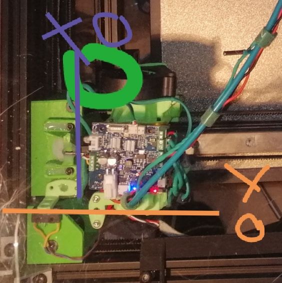
Can you show an image marked up with where the motors driven by the 02,03,04 drivers are positioned?
-
@Frederik
Add an M291 between the M409 and the if statement. I have updated the macro below with thisM291 P{move.calibration.initial.deviation} S3Based upon these values
M208 X0 Y0 Z0 S1                 ; set axis minima
M208 X415 Y395 Z400 S0           ; set axis maxima
G10 P0 X0 Y0 Z0                  ; set tool 0 axis offsets
the nozzle should be considered at x0 y0 and the BLTouch at x-38 y-10 in the comment below.
when my printhead is homed at x0 y0 (left front corner) the bltouch is around x-3 y-2
the nozzle x35 y8
This
G31 P1000 X0 Y0 Z0.81 ; BLTouch offsetshould be updated to this
G31 P1000 X-38 Y-10 Z0.81 ; BLTouch offset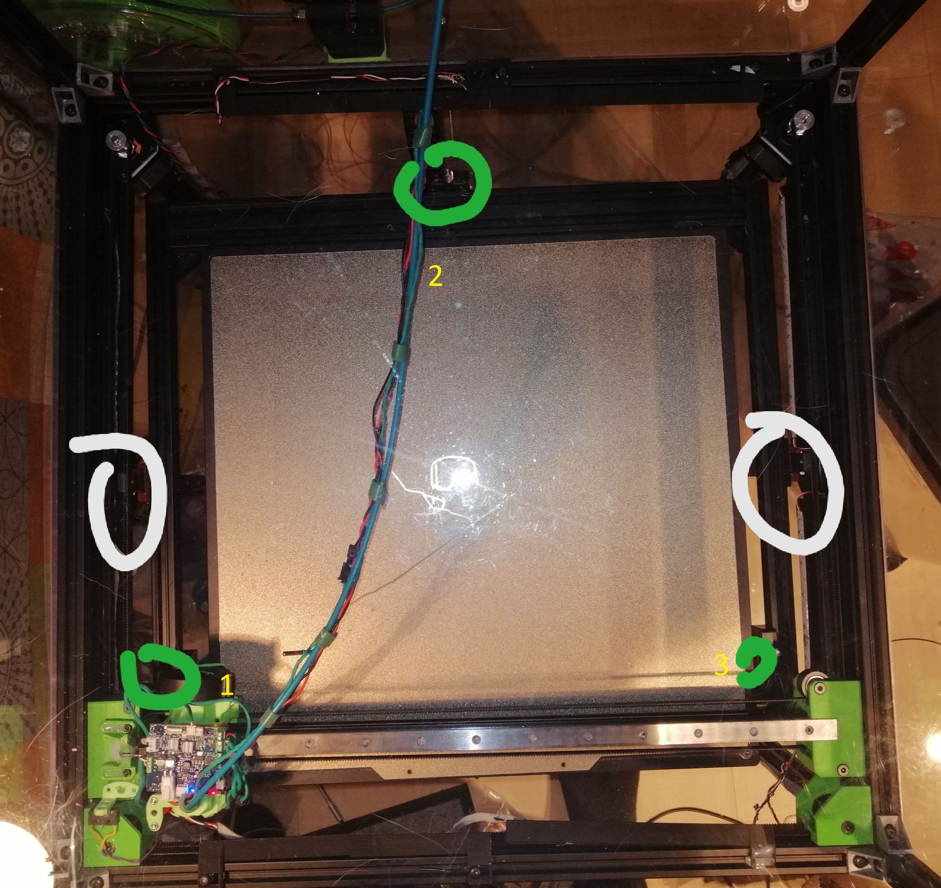
For M671 move the tool head to the position indicated by the (1) of x0 y(align the nozzle to the spindle). Measure from the center of the nozzle to the center of the spindle and subtract that number from x0. The Y value will be the Y position as indicated by the DWC tool position.Next move tool head to position 2 of x(align the nozzle to the spindle) y395. Measure from the center of the nozzle to the center of the spindle and add that number to y395. The X value will be the X position as indicated by the DWC tool position.
Next move tool head to position 3 of x415 y(align the nozzle to the spindle). Measure from the center of the nozzle to the center of the spindle and add that number to x415. The Y value will be the Y position as indicated by the DWC tool position.
Update the M671 with the values collected from the above steps.
M671 X0:215:450 Y80:450:80 S5 ; Position of LeadscrewsNext copy your first G30 command from the 3point calibration
G30 P0 X40 Y80 Z-99999to the console and send it the printer. Once the command has finished record the tool position as indicated by the DWC. Use this x and y value in a G1 x## y## command at the beginning of the 3point calibration followed by G30 to set the z height.
Update the 3point calibration macro to something like
M203 Z100 ; set a low z max speed to increase accuracy. Run multiple G30 S-1 to determine the speed needed to achieve the accuracy you need.
G28
while true
        G1 X## Y## ; enter the tool position as indicated by the DWC after running the first G30 command in the 3point calibration
        G30 ; sets the first point of the 3point calibration as Z0
	G30 P0 X40 Y80 Z-99999          ; Probe near the front left lead-screw
        G30 P1 X215 Y395 Z-99999        ; Probe near the rear lead screw
        G30 P2 X415 Y80 Z-99999 S3      ; Probe near the front right lead-screw
	M409 K"move.calibration.initial.deviation" ;displays deviation in console
        M400 ; wait for move to complete
        M291 P{move.calibration.initial.deviation} S3 ;displays deviation value
	if move.calibration.initial.deviation <= 0.001  ; change the 0.001 to your needed value
		echo "Passed"
                M203 Z1000 ; set this z max speed to match your config file. Note if you cancel this macro by selecting the cancel button on the M291 message box this command will not run. You will need to run this command from the console to restore the max z speed
		break
	continue
Follows these steps above to double check all your setting are correct. Lets the 3point calibration macro run until the deviation no longer decreases and post the results.
@Phaedrux
This is my understanding of the calibration process for 3 motor Z axis calibration.
If something is not correct please update it. This is the process I used to set mine up and it works perfectly.Edit: {
Added M203 to start and end of macro to increase probe accuracy.@3dML said in RRF3.2Beta4.1 Heightmap vs. Spindle/Driver Mapping:
@Frederik
I have found that slowing down the maximum Z speed can help with tolerance.}
-
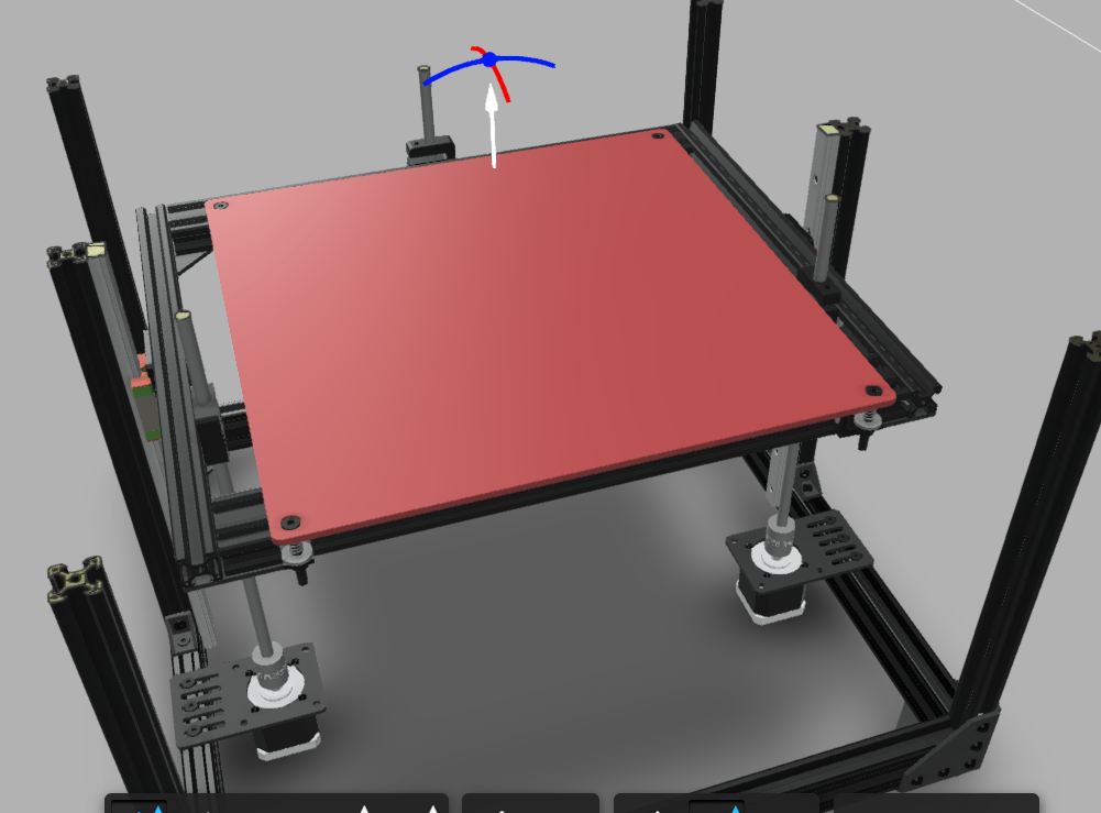
this is the online fusion 360 CAD Model of my build. perhaps it helps to show the position oh everything and offsets ....
https://myhub.autodesk360.com/ue2c6242f/g/shares/SH56a43QTfd62c1cd9689aec54c27a170106
-
@Frederik
The drawing looks correct. My above post still applies.Based on these values
M208 X0 Y0 Z0 S1                 ; set axis minima
M208 X415 Y395 Z400 S0           ; set axis maxima
G10 P0 X0 Y0 Z0                  ; set tool 0 axis offsets
all offsets are relative to nozzle position with the tool at x0 y0.
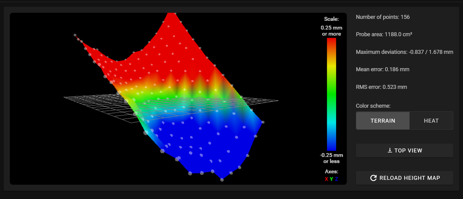
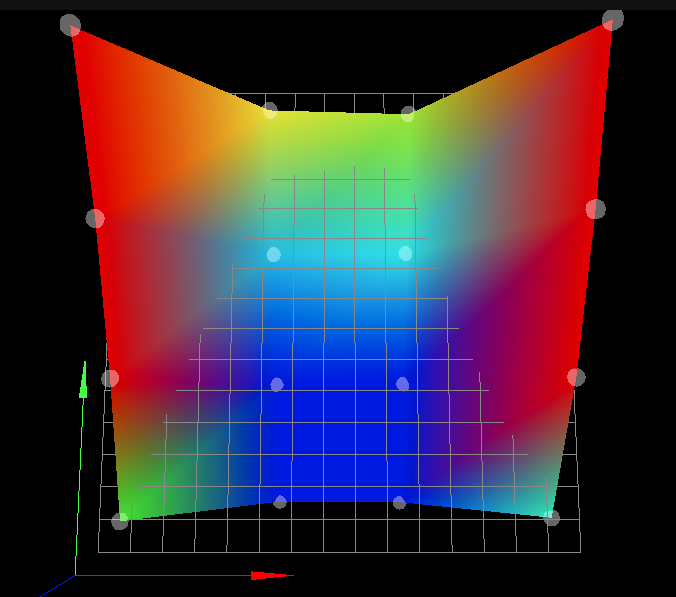
Base on that drawing and your height map I'd say the bed has a large sag along the Y axis.

In this image your 3point calibration deviation is close to 0 but the sag in the bed is causing the skew in the Heightmap. -
@3dML ok, i will post the values as soon as im finished. i will send the manufacturer a photo, perhaps its was damaged during shipping
-
-
@Frederik
Post a picture of the current mount you are using to mount the bed to the z sub-frame. If you are using the mounts I think you are they may be be the cause of sum of the sag. -
@3dML Good Morning,
Merry Christmas
The last if loop after modifying the accel values of Z to 20 and max speed to 100
M98 P"0:/macros/1 test if loop - Z deviation new"
Leadscrew adjustments made: 0.351 -1.187 0.554, points used 3, (mean, deviation) before (0.049, 0.626) after (0.000, 0.000)
{"key":"move.calibration.initial.deviation","flags":"","result":0.626}
Leadscrew adjustments made: 0.346 -0.771 0.107, points used 3, (mean, deviation) before (-0.010, 0.392) after (-0.000, 0.000)
{"key":"move.calibration.initial.deviation","flags":"","result":0.392}
Leadscrew adjustments made: 0.093 -0.459 0.023, points used 3, (mean, deviation) before (-0.066, 0.200) after (0.000, 0.000)
{"key":"move.calibration.initial.deviation","flags":"","result":0.200}
Leadscrew adjustments made: 0.077 -0.390 -0.087, points used 3, (mean, deviation) before (-0.095, 0.158) after (0.000, 0.000)
{"key":"move.calibration.initial.deviation","flags":"","result":0.158}
Leadscrew adjustments made: -0.032 -0.217 -0.052, points used 3, (mean, deviation) before (-0.084, 0.067) after (0.000, 0.000)
{"key":"move.calibration.initial.deviation","flags":"","result":0.067}
Leadscrew adjustments made: -0.170 -0.222 -0.008, points used 3, (mean, deviation) before (-0.125, 0.068) after (0.000, 0.000)
{"key":"move.calibration.initial.deviation","flags":"","result":0.068}
Leadscrew adjustments made: -0.142 -0.175 -0.105, points used 3, (mean, deviation) before (-0.137, 0.022) after (-0.000, 0.000)
{"key":"move.calibration.initial.deviation","flags":"","result":0.022}
Leadscrew adjustments made: -0.15 actual 2 -0.165 -0.158, points used 3, (mean, deviation) before (-0.157, 0.004) after (0.000, 0.000)
{"key":"move.calibration.initial.deviation","flags":"","result":0.004}
Leadscrew adjustments made: -0.164 -0.177 -0.151, points used 3, (mean, deviation) before (-0.163, 0.008) after (-0.000, 0.000)
{"key":"move.calibration.initial.deviation","flags":"","result":0.008}
Leadscrew adjustments made: -0.182 -0.158 -0.160, points used 3, (mean, deviation) before (-0.168, 0.008) after (-0.000, 0.000)
{"key":"move.calibration.initial.deviation","flags":"","result":0.008}
Leadscrew adjustments made: -0.165 -0.169 -0.172, points used 3, (mean, deviation) before (-0.168, 0.002) after (0.000, 0.000)
{"key":"move.calibration.initial.deviation","flags":"","result":0.002}
Passed
My NOZZLE !!! is now x0 Y0, like you mentioned, and bltouch x-35 y-15 d, i would thay after looking at the different values, the measurements are getting overall closer and more consistent
Yesterday i changed the mounting from silicone spacers back to the standard springs from the Kit. now its mounted 1:1 like the CAD above wiht 4 springs at the corners