BL touch and how to define area for mesh compensation properly
-
Hi guys,
Can somebody explain to me please how to set properly area for mesh compensation.
This is how is set now, you can see what my left bottom point is -85 mm, made especially so my BL touch will measure the edge of build plate. It has set offset in Y direction from nozzle of Y-47.06.
And this is my mesh grid coordinates defined.
M557 X0:295 Y-85:150 S30 ; define mesh gridPlus my axis limits:
; Axis Limits
M208 X-16 Y-45 Z0 S1                          ; set axis minima
M208 X321 Y208 Z305 S0                        ; set axis maxima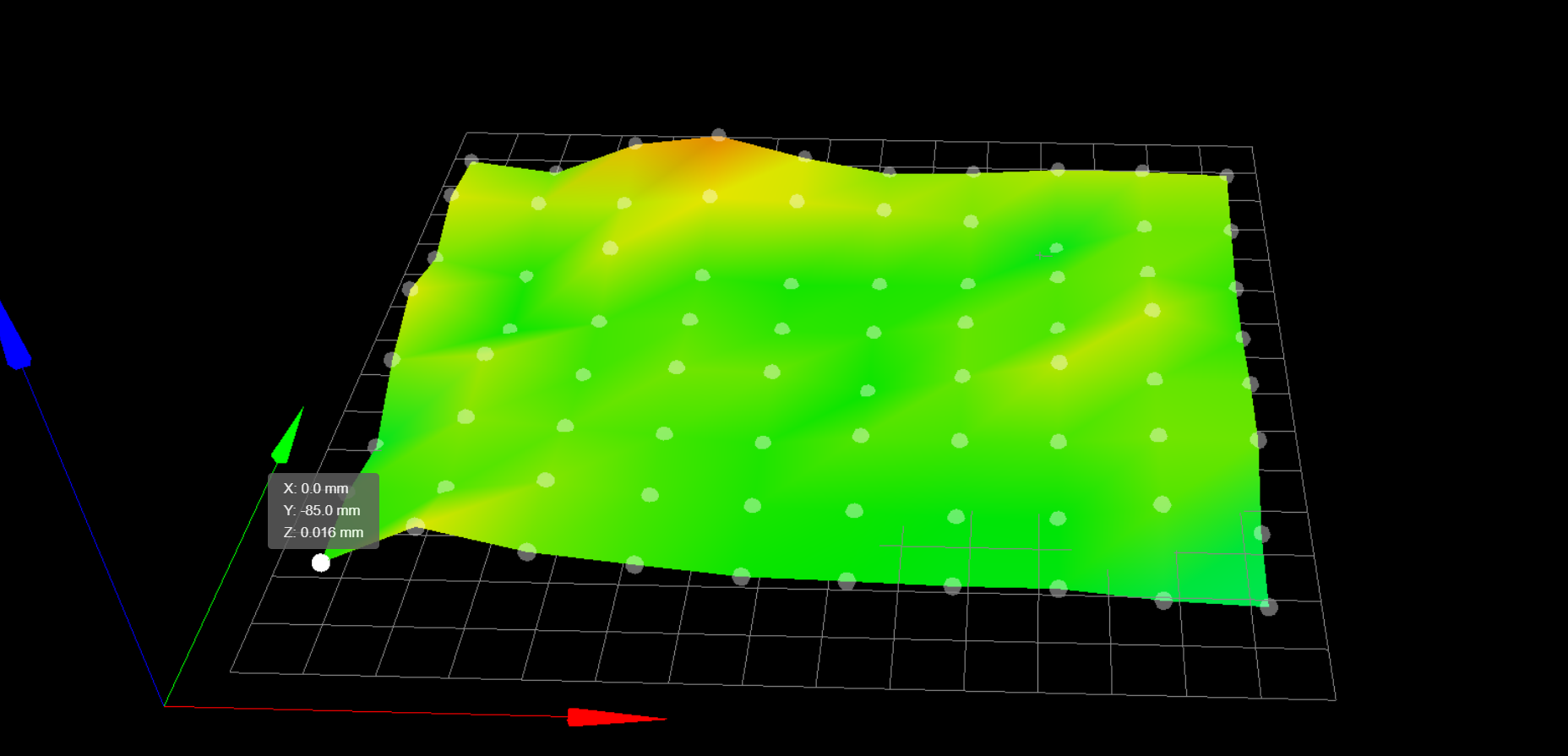
My concern here is if my nozzle is actually compensating at the right location if I look on to Y-85 in my first point. I do have feeling what the whole bed should be moved back by 85 mm on Y, to correctly represent compensation underneath the nozzle. I am not sure if I gave a clear issue here, but maybe somebody with more experience sees the issue here?
There is my main files:
; Configuration file for Duet WiFi (firmware version 2.03)
; executed by the firmware on start-up
;
; generated by RepRapFirmware Configuration Tool v2.1.4 on Thu Jan 02 2020 22:17:48 GMT+0100 (Central European Standard Time)

; General preferences
G90                                             ; send absolute coordinates...
M83                                             ; ...but relative extruder moves
M550 P"own"                                     ; set printer name

M667 S1                                         ; select CoreXY mode

; Network
M552 S1                                         ; enable network
M586 P0 S1                                      ; enable HTTP
M586 P1 S0                                      ; disable FTP
M586 P2 S0                                      ; disable Telnet

; Drives
M569 P0 R-1
M569 P0 S1                                      ; physical drive 0 goes forwards
M569 P1 S1                                      ; physical drive 1 goes forwards
M569 P2 S1                                      ; physical drive 2 goes forwards
M569 P3 S1                                      ; physical drive 3 goes backwards
M569 P4 S1                                      ; physical drive 4 goes forwards
M584 X4 Y1 Z2 E3:0                             ; set drive mapping
M350 X16 Y16 Z16 E16:16 I1                      ; configure microstepping with interpolation
M92 X200.8 Y200.8 Z400 E415:415			; set steps per mm
M566 X500 Y500 Z20 E1500.00:1500.00      	; set maximum instantaneous speed changes (mm/min)
M203 X15000 Y15000.00 Z600 E13000.00:13000.00   ; set maximum speeds (mm/min)
M201 X4000 Y4000 Z100 E8000.00:8000.00      	; set accelerations (mm/s^2)
M204 P1000 T1000				; printing acceleration
M906 X1300 Y1300 Z1500 E600:600 I30             ; set motor currents (mA) and motor idle factor in per cent
M84 S90                                         ; Set idle timeout

; Axis Limits
M208 X-16 Y-45 Z0 S1                                ; set axis minima
M208 X321 Y208 Z305 S0                        ; set axis maxima

; Endstops
M574 Z1 S2                		     ; set active low and disabled endstops
M574 X1 S0                			  ; set active high endstops
M574 Y2 S0

; Z-Probe
M307 H3 A-1 C-1 D-1                             ; disable heater on PWM channel for BLTouch
M558 A10 S0.01 P9 H3 F60 T5000 R0.3                          ; set Z probe type to bltouch and the dive height + speeds
G31 P25 X0 Y-47.06 Z2.150               ; set Z probe trigger value, offset and trigger height (positive value brings bed closer)
M557 X0:295 Y-85:150 S30                      ; define mesh grid

; Heaters
M141 H5 					; heater 5 is the chamber heater
M305 X1 P5 B4725 C7.060000e-8 			; heater 5 is monitored by a E3D thermistor
;M307 H5 C99000 D0.05 S1.00 V0.0 B0		; disable bang-bang control for the chamber heater
M143 H5 S90
;M307 H0 B0 S1.00                        	; disable bang-bang mode for the bed heater and set PWM limit
M305 P0 T100000 B4138 R4700             	; set thermistor + ADC parameters for heater 0
M143 H0 S150                            	; set temperature limit for bed heater 0 to 150C
M305 P1 X200                                    ; configure PT100 for heater 1
M143 H1 S480                                    ; set temperature limit for heater 1 to 480C
M305 P2 X201                                    ; configure PT100 for heater 2
M143 H2 S300                                    ; set temperature limit for heater 2 to 300C

; Fans
M106 P0 S0 I0 F20 H-1                          ; set fan 0 value, PWM signal inversion and frequency. Thermostatic control is turned off
M106 P1 S1 I0 F20 H-1                          ; set fan 1 value, PWM signal inversion and frequency. Thermostatic control is turned off
M106 P2 S1 I0 F20 H-1                          ; set fan 2 value, PWM signal inversion and frequency. Thermostatic control is turned off

; Tools
M563 P0 S"Left" D0 H1 F-1                       ; define tool 0
G10 P0 X0 Y0 Z0                                 ; set tool 0 axis offsets
G10 P0 S0 R175 									; Set tool 0 active and standby temperatures
M563 P1 S"Right" D1 H2 F-1                      ; define tool 1
G10 P1 X20.09 Y0 Z0                               ; set tool 1 axis offsets
G10 P1 S0 R175 									; Set tool 0 active and standby temperatures

; Custom settings are not defined

; Miscellaneous
                                           ; load saved parameters from non-volatile memory
M501
; bed.g ; called to perform automatic bed compensation via G32 ; ; generated by RepRapFirmware Configuration Tool v2.1.4 on Thu Jan 02 2020 22:17:48 GMT+0100 (Central European Standard Time) M561 ; clear any bed transform G29 ; probe the bed and enable compensation; homeall.g ; called to home all axes ; Home XY for Z homing G91 ; relative positioning M913 X50 Y50 ; set X Y motors to 50% of their normal current for homing G1 S1 X-321 Y272.5 F4000 ; course home X or Y G1 S1 X-321 F4000 ; course home X G1 S1 Y272.5 F4000 ; course home Y G1 X2 Y-3 F4000 ; move away from the endstops G1 S1 X-321 F200 ; fine home X G1 S1 Y272.5 F200 ; fine home Y M913 X100 Y100 ; set X Y motors to 100% of their normal current ; Z homing section follows G90 ; absolute positioning G1 X146 Y106 F4000 ; Move x and Y axis over to bed center so probe is on top of bed ; Probe the bed M558 A1 F600 ; Set single probing at faster feed rate G30 ; Do a single probe to quickly home Z axis M558 A10 F100 ; Set multi probing at slower feed rate G30 ; Probe again to get a more accurate position ; Probe the bed ; Move X and Y back Home G1 X0 Y0Industrial 3D printing service in the Netherlands - gagatstudio.com
-
@felt342 said in BL touch and how to define area for mesh compensation properly:
M208 X-16 Y-45 Z0 S1
Y-45 would mean that your nozzle tip is 45mm off the edge of the print surface when the endstop is triggered during homing. Is that correct?
And your BLTouch is 47mm in front of the nozzle tip?
If that's the case, I don't think you'd want your grid spacing to try and move all the way to -85 on Y because that would be beyond where the endstop is triggered. You'd want it only as far as the reachable print surface which would be Y0.
This is assuming that 0,0 origin point is on the front left corner of the print surface.
-
That is correct my nozzle is offset 47 mm from BL touch.
With these settings I am getting BL touch measurement when nozzle is located on top of 0,0 origin. But in that case BL touch is measuring 47 mm in front which I think is not very accurate representation of the mesh.
; Axis Limits
M208 X-20 Y0 Z0 S1                                ; set axis minima
M208 X321 Y208 Z305 S0                        ; set axis maxima
; Z-Probe G31 P25 X0 Y-47.06 Z2.150 ; set Z probe trigger value, offset and trigger height (positive value brings bed closer) M557 X-6:290 Y-47:150 S30 ; define mesh grid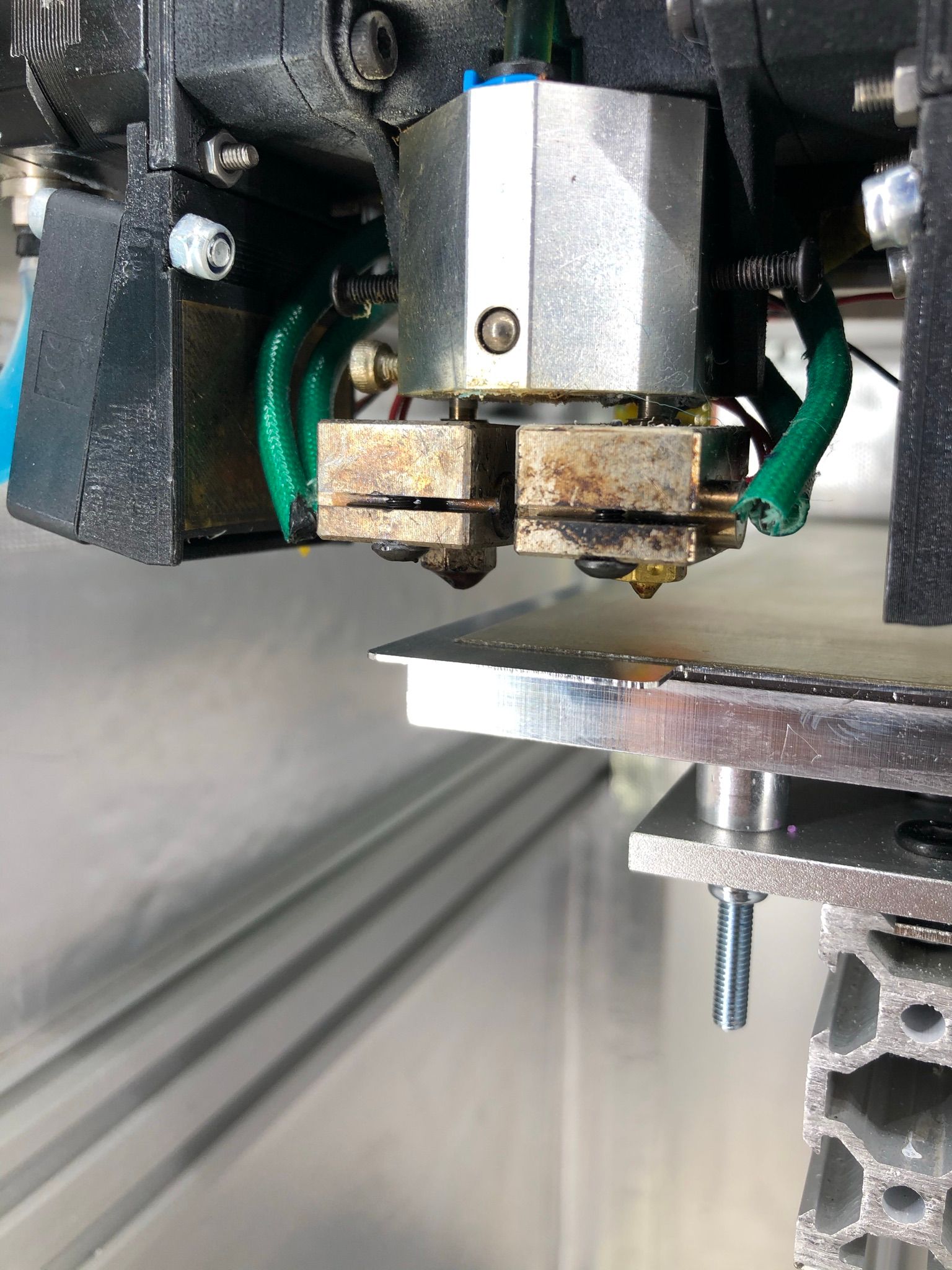
======================================================================================================================
With these settings I am getting BL touch measurement when nozzle is moving to Y47mm. In that case BL touch is measuring at 47+47=Y94 coordinates... which is not good.
; Axis Limits
M208 X-20 Y0 Z0 S1                                ; set axis minima
M208 X321 Y208 Z305 S0                        ; set axis maxima
; Z-Probe G31 P25 X0 Y-47.06 Z2.150 ; set Z probe trigger value, offset and trigger height (positive value brings bed closer) M557 X-6:290 Y0:150 S30 ; define mesh grid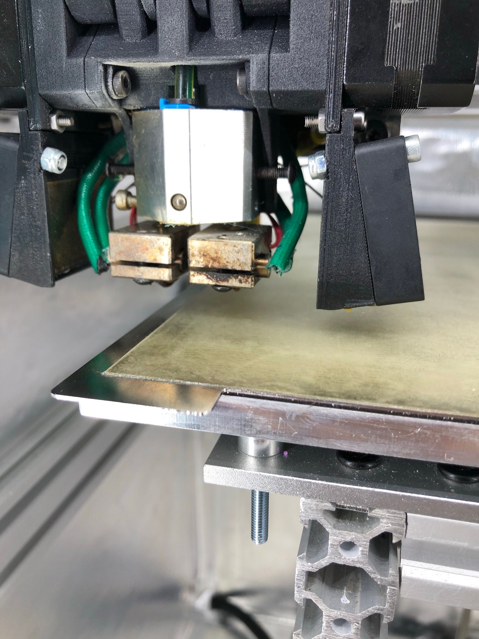
======================================================================================================================
With these settings I am getting BL touch measurement when the nozzle is located 47 mm in front of the bed (in the air). In that case BL touch is measuring at 0,0 coordinates which I think is right but will it be an accurate representation for the nozzle. Or it will mean what the whole bed mesh will be shifted 47 mm and when nozzle will start print at 0,0 it will use mesh compensation for this point shifted by 47 mm in a mesh?
; Axis Limits
M208 X-20 Y-85 Z0 S1                                ; set axis minima
M208 X321 Y208 Z305 S0                        ; set axis maxima
; Z-Probe G31 P25 X0 Y-47.06 Z2.150 ; set Z probe trigger value, offset and trigger height (positive value brings bed closer) M557 X-6:290 Y-85:150 S30 ; define mesh grid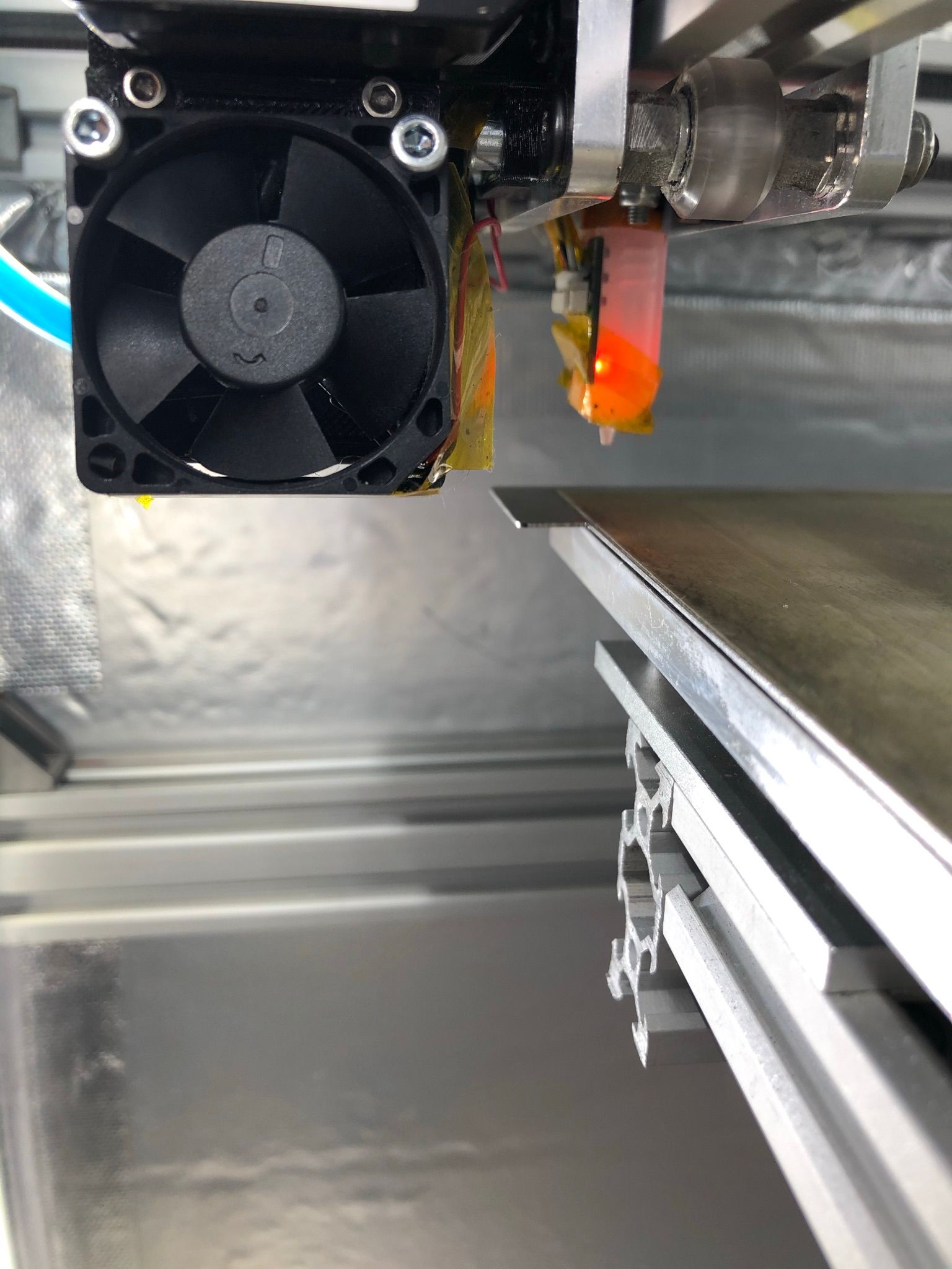
I hope it is clearer now more or less
")
Moving BL touch closer to the nozzle will do the trick probably what I want, but I don't want to move BL touch so close to the nozzle or any heat as it's already in harsh environment as my heated chamber goes to 80 degrees...
Industrial 3D printing service in the Netherlands - gagatstudio.com
-
@felt342
For the bed compensation it doesn't matter how far or close the sensor is from the nozzle. It calculates the compensation based on the offsets in G31 X..Y..Z..
Only for the probeable area it makes a difference, because you can't probe the whole bed with a 47mm offset. That's the reason why we try to put the sensors as close as possible. -
Thank you.
Meaning what I should stick to this setting to make it right? Which locate the nozzle on top of 0,0 origin when it starts probe.; Axis Limits M208 X-20 Y0 Z0 S1 ; set axis minima M208 X321 Y208 Z305 S0 ; set axis maxima ; Z-Probe G31 P25 X0 Y-47.06 Z2.150 ; set Z probe trigger value, offset and trigger height (positive value brings bed closer) M557 X-6:290 Y-47:150 S30 ; define mesh gridIndustrial 3D printing service in the Netherlands - gagatstudio.com
-
@felt342
I think you will get warnings from the M557 grid, because y-47 is outside of the bed. You can define the grid from the BLTouch point of view, don't care about the nozzle. The firmware know the offset, so when you ask to probe 'G30 X10 Y10' that's the probe position.