Duet3D Logo Duet3D
    • Tags
    • Documentation
    • Order
    • Register
    • Login
    1. Home
    2. felt342
    • Profile
    • Following 0
    • Followers 0
    • Topics 16
    • Posts 136
    • Best 12
    • Controversial 0
    • Groups 0

    felt342

    @felt342

    19
    Reputation
    5
    Profile views
    136
    Posts
    0
    Followers
    0
    Following
    Joined Last Online
    Website gagatstudio.com Location the Netherlands

    felt342 Unfollow Follow

    Best posts made by felt342

    • WIP CoreXY with heated chamber

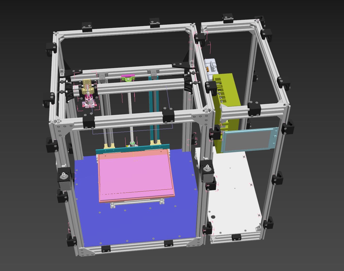
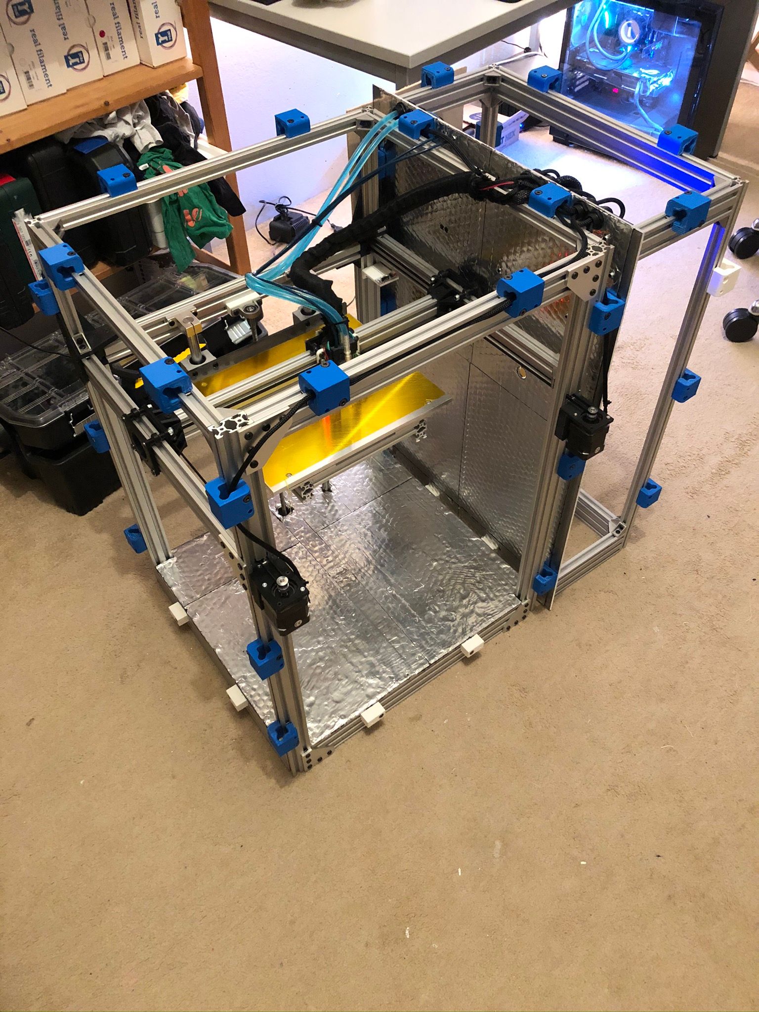
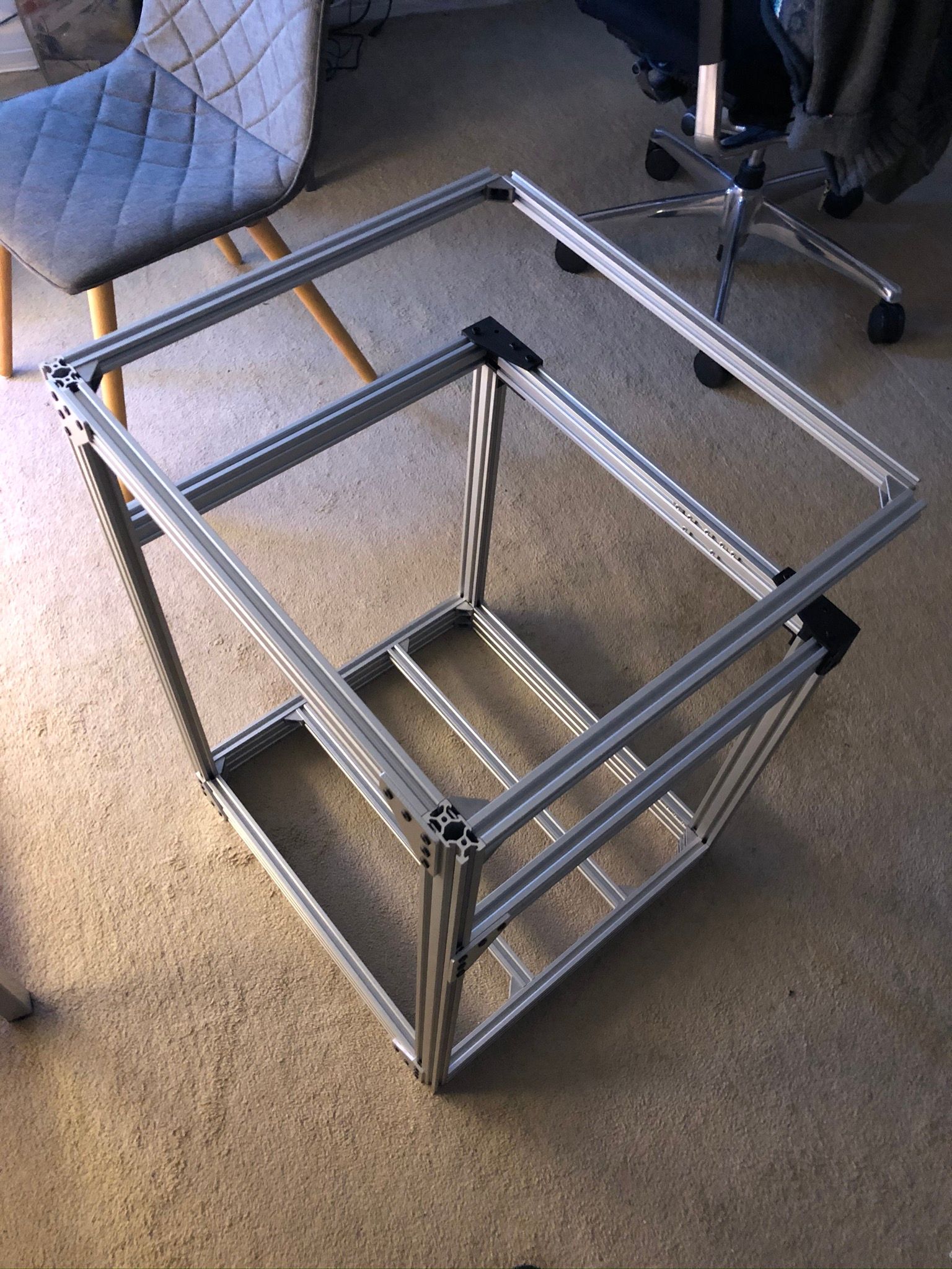
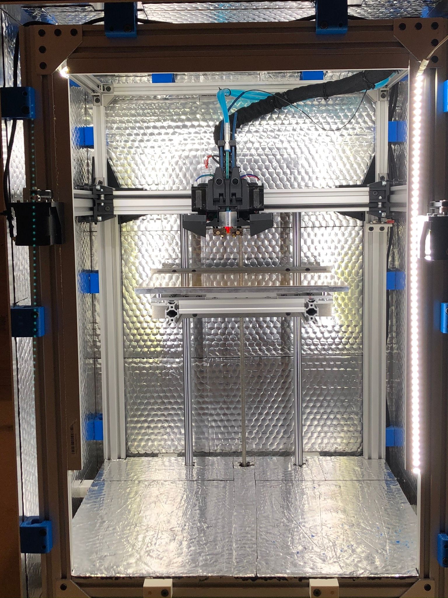
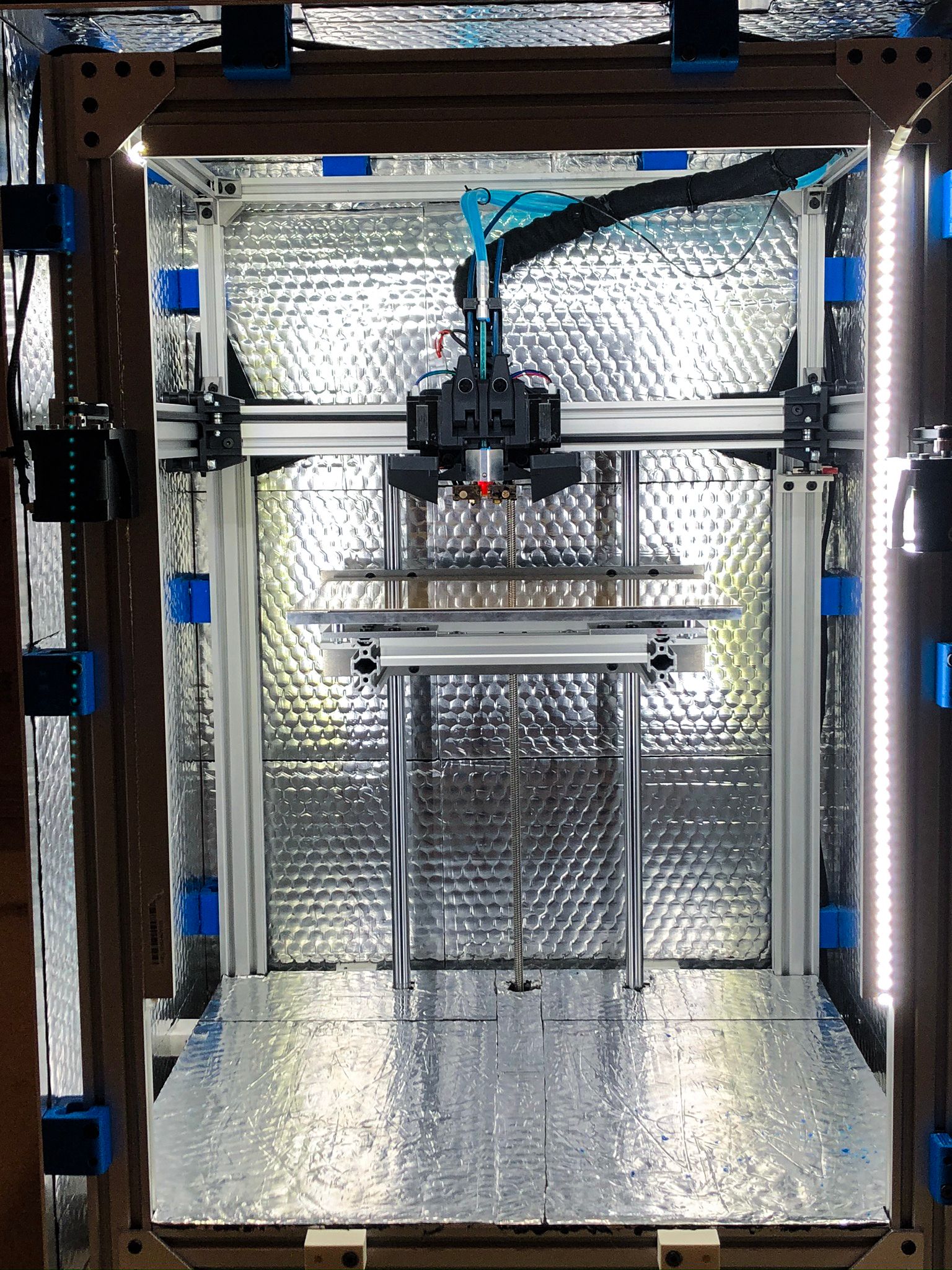
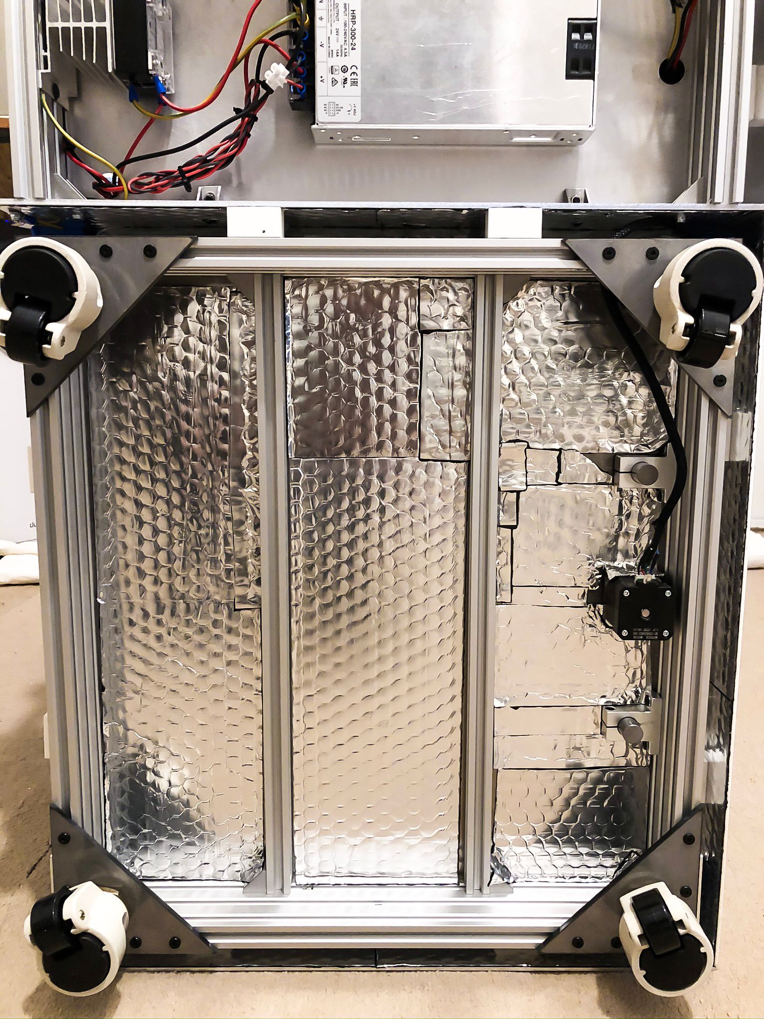
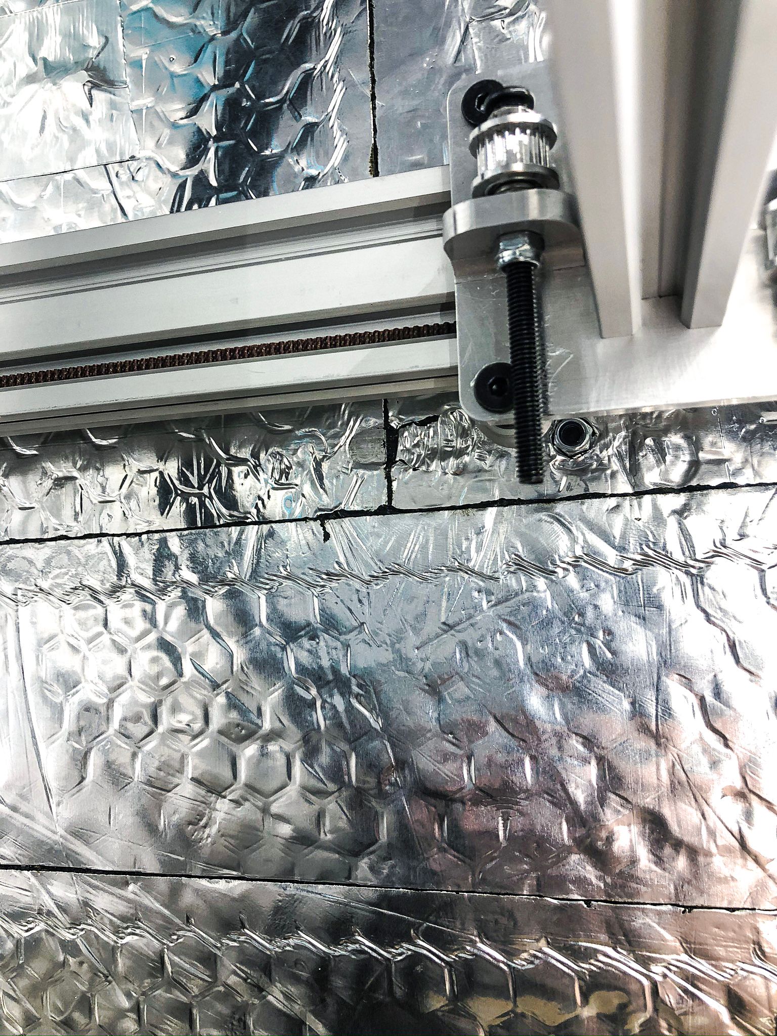
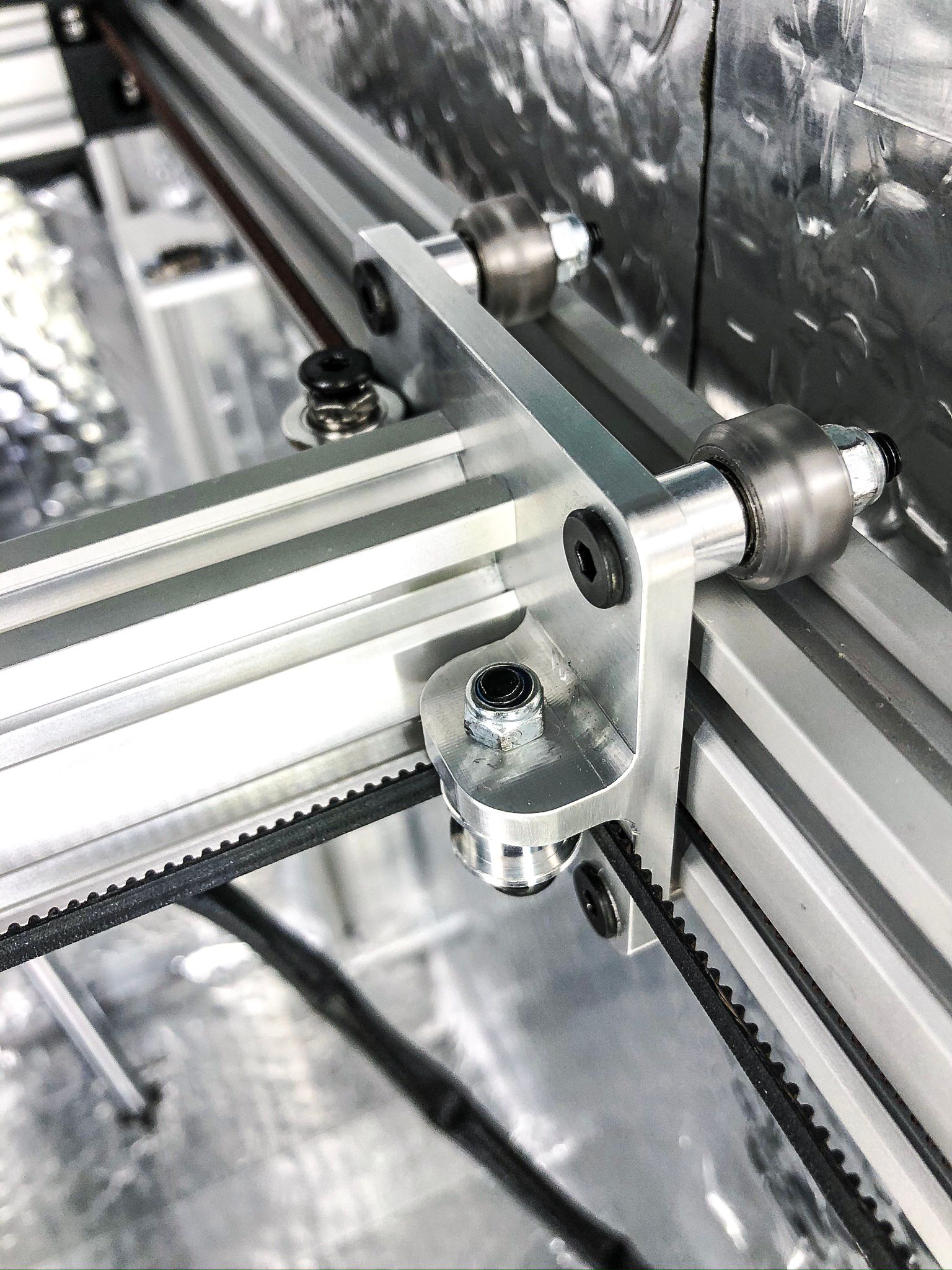
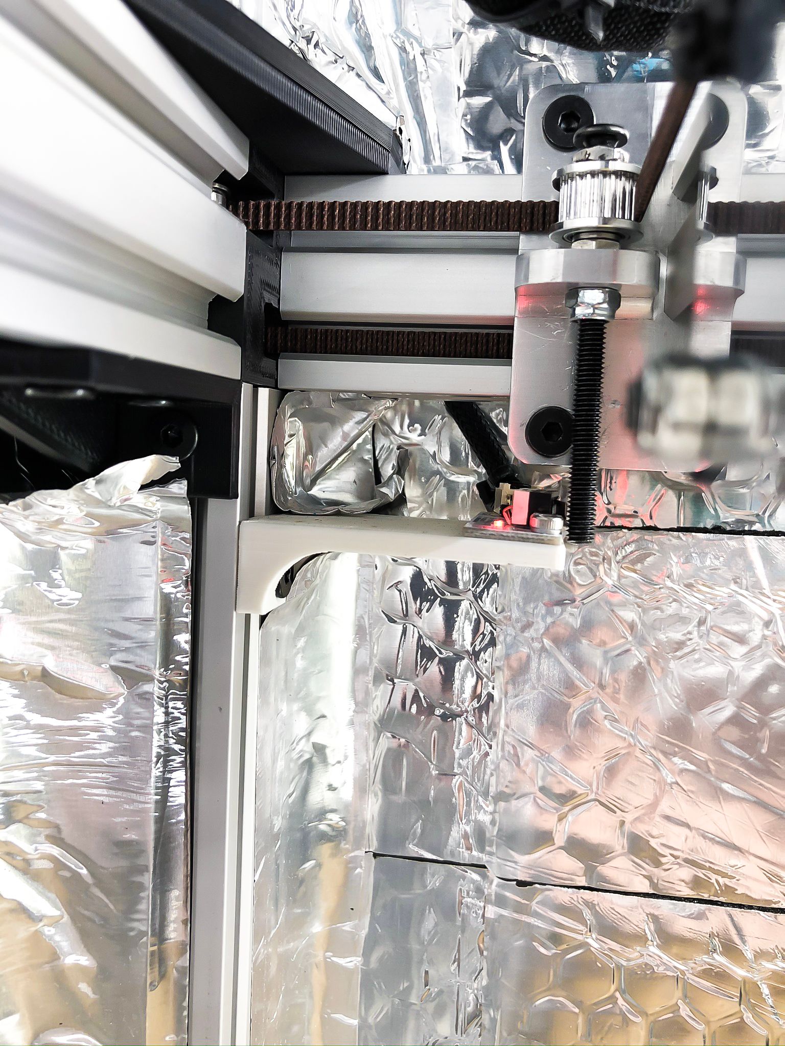
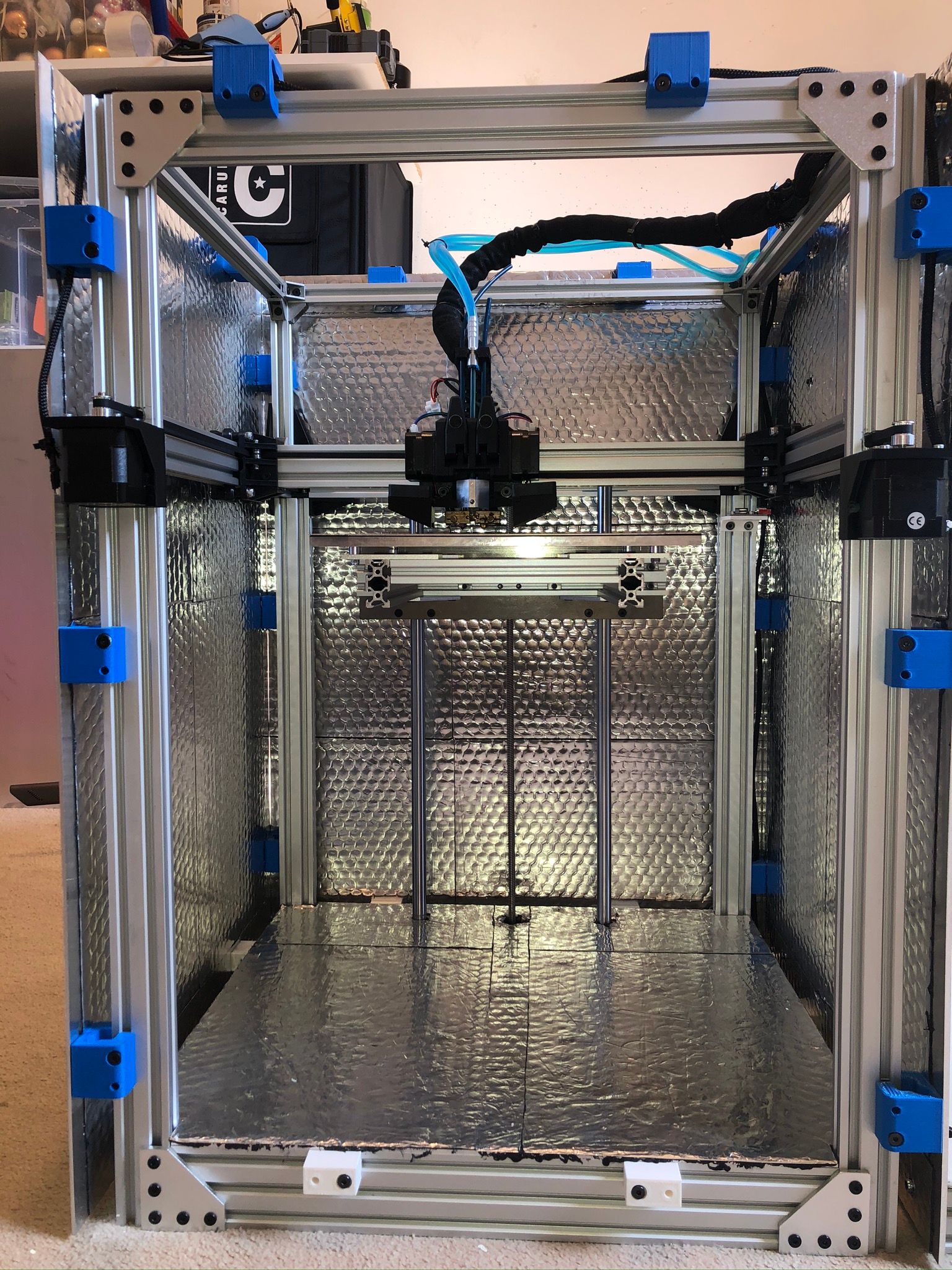
      I am working on Core XY which needed to have a certain specification, this is my first build ever:

      • 1 Z-axis for simplicity and clean look;
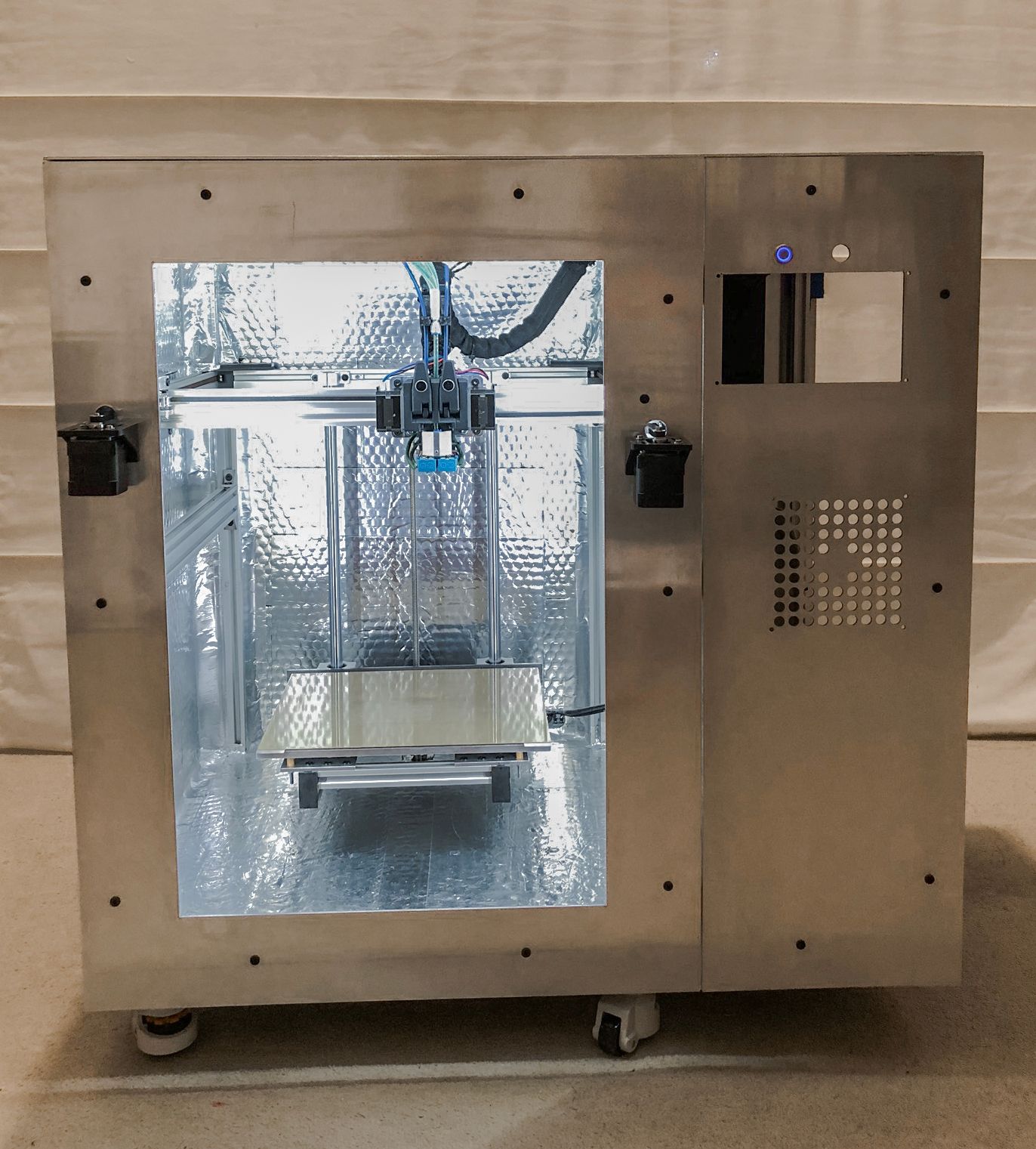
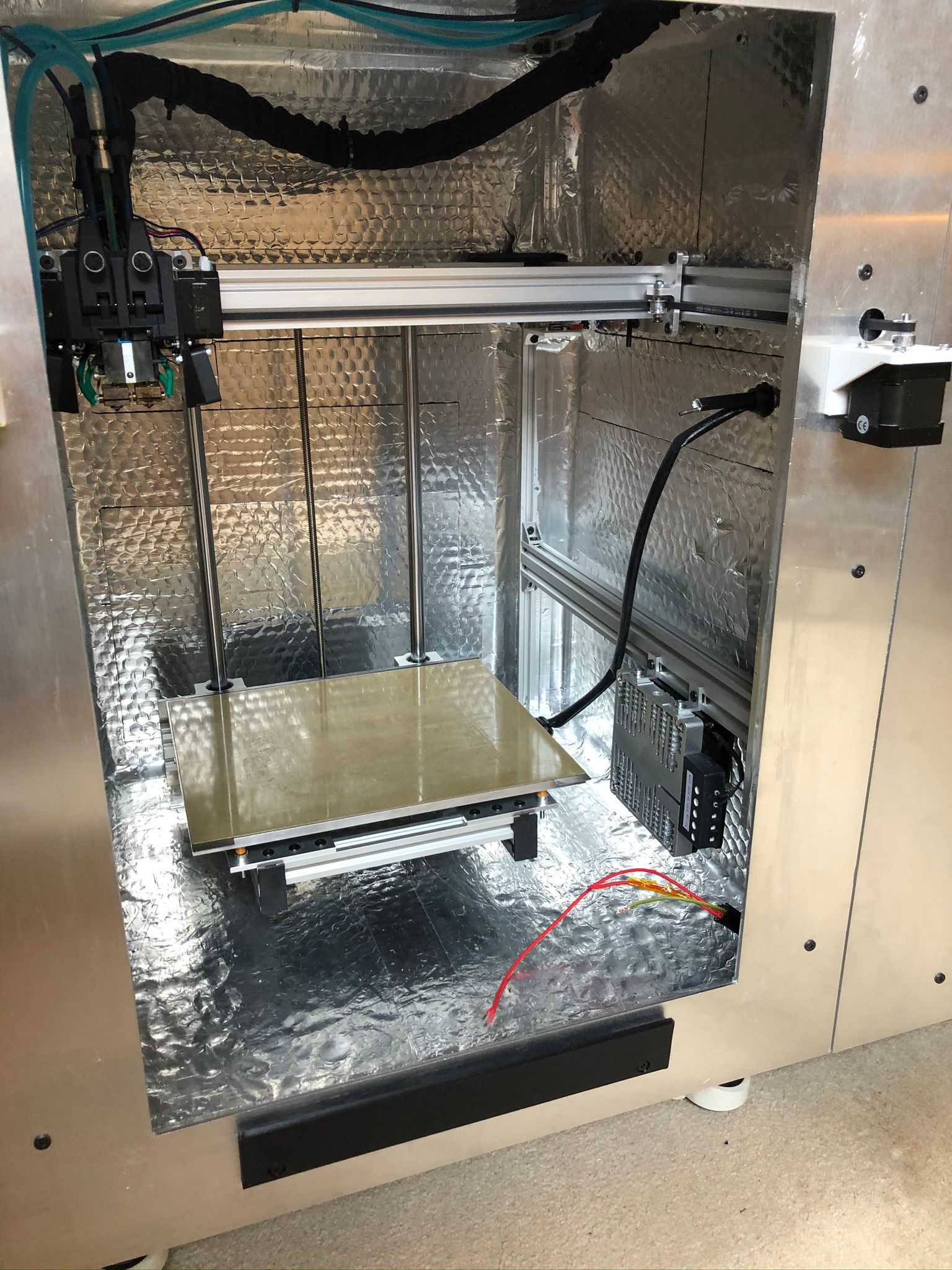
      • Build volume 300x250x300;
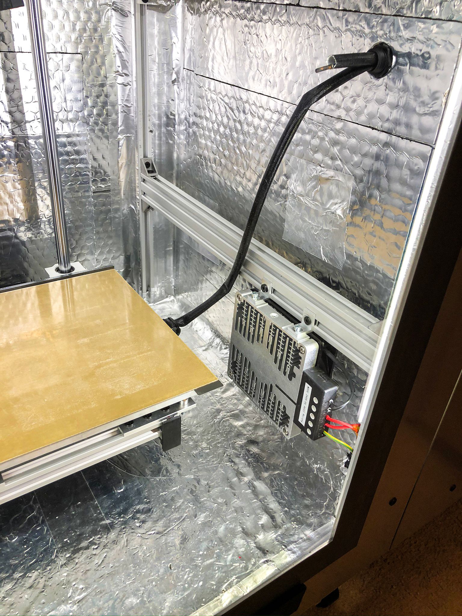
      • Heated Chamber 70C;
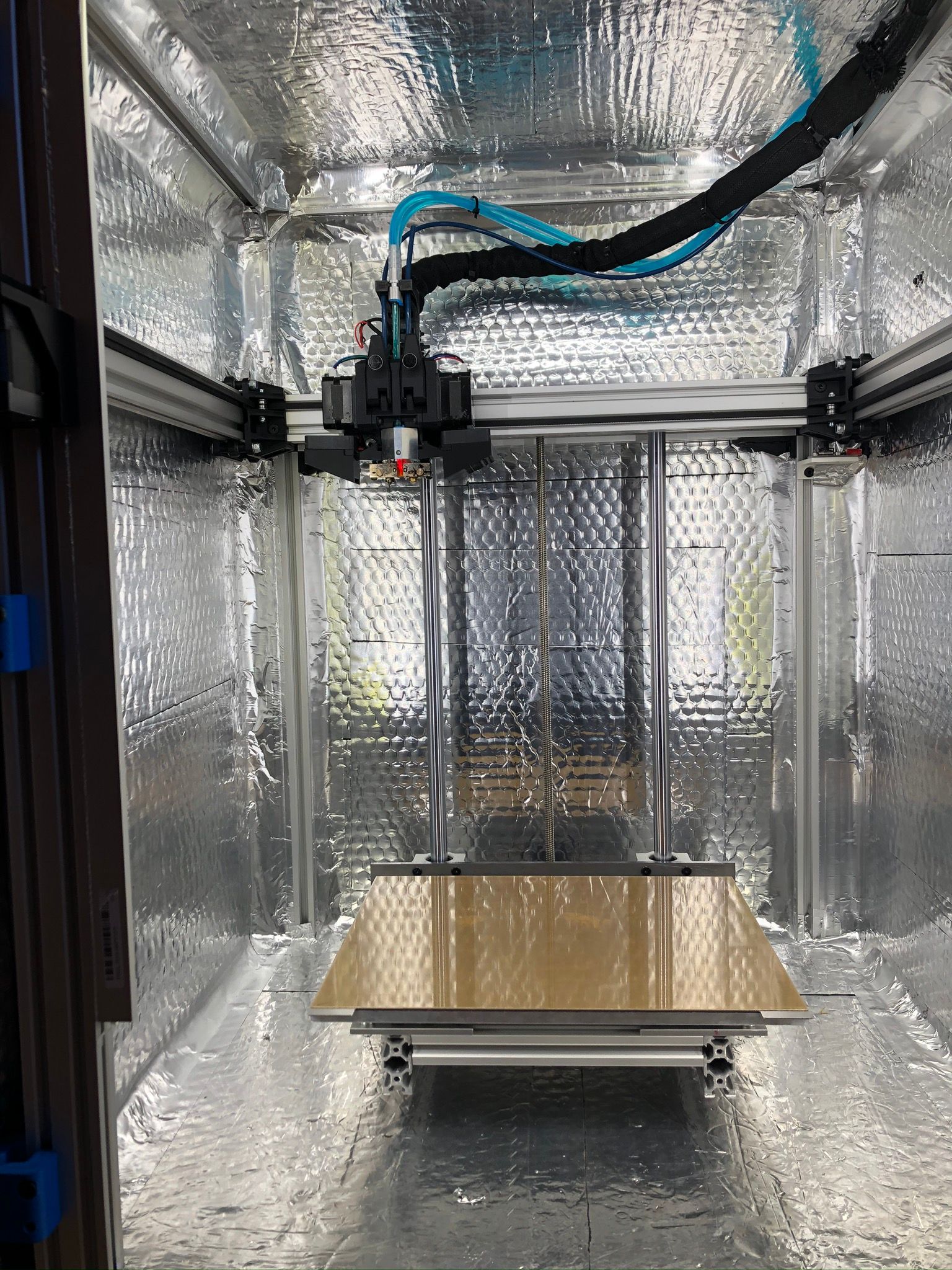
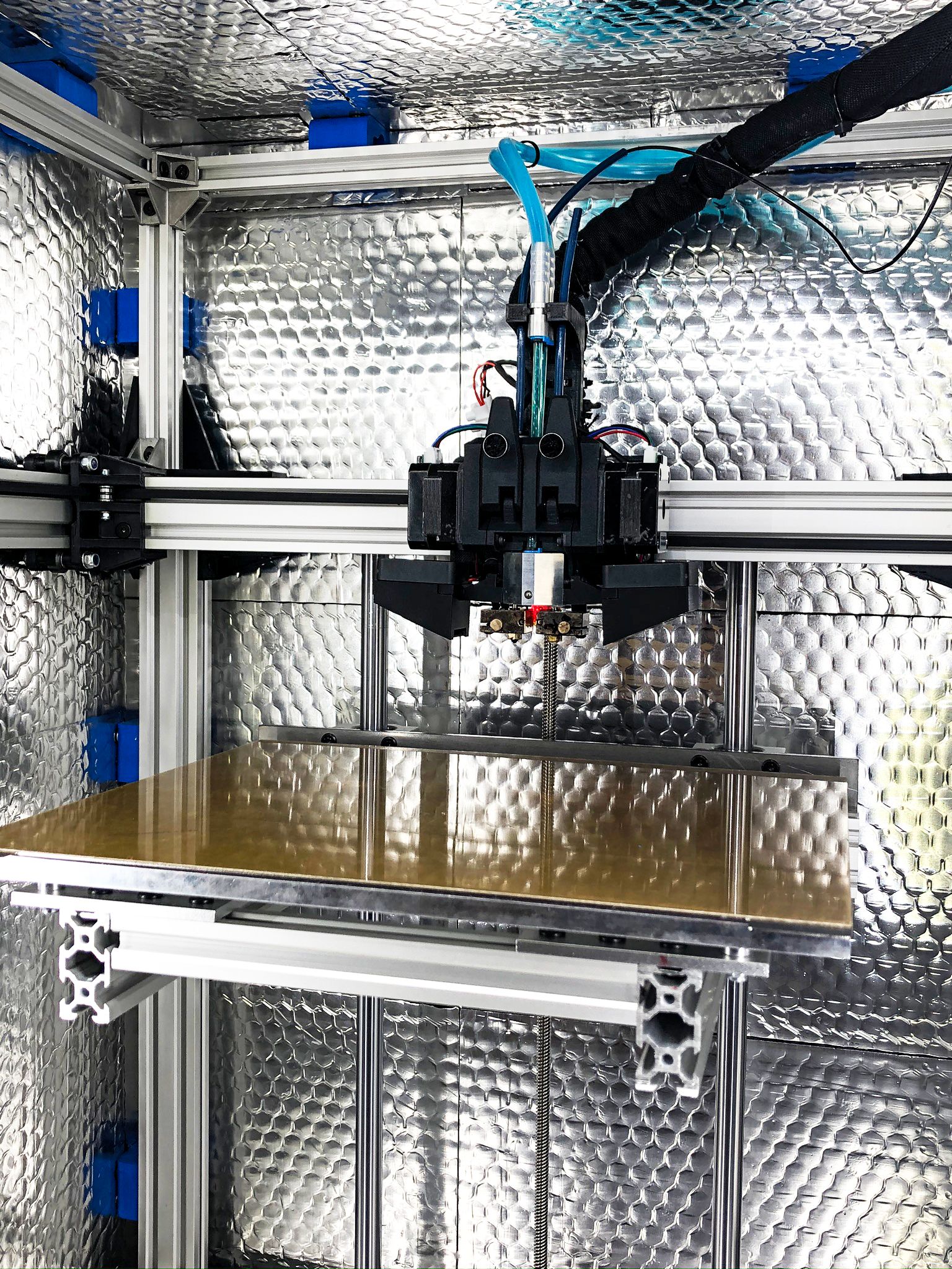
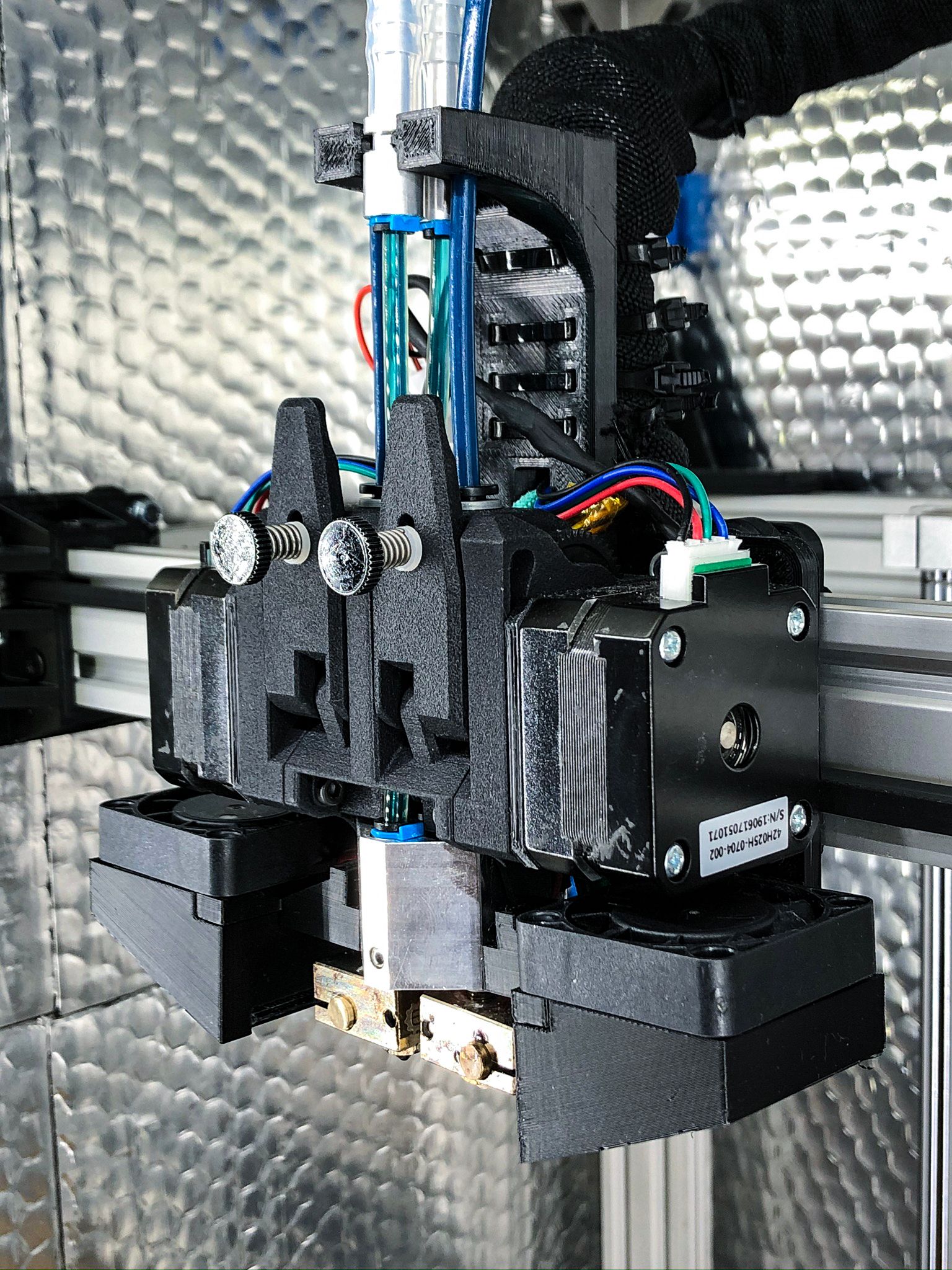
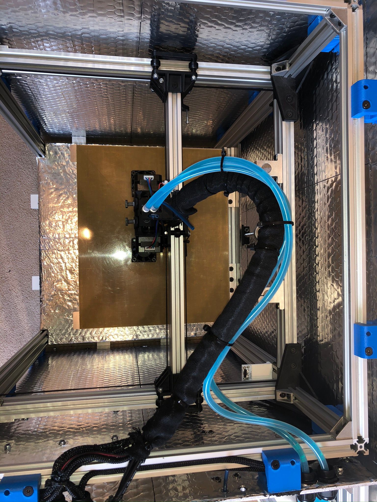
      • Dual extrusion mainly for water-soluble supports;
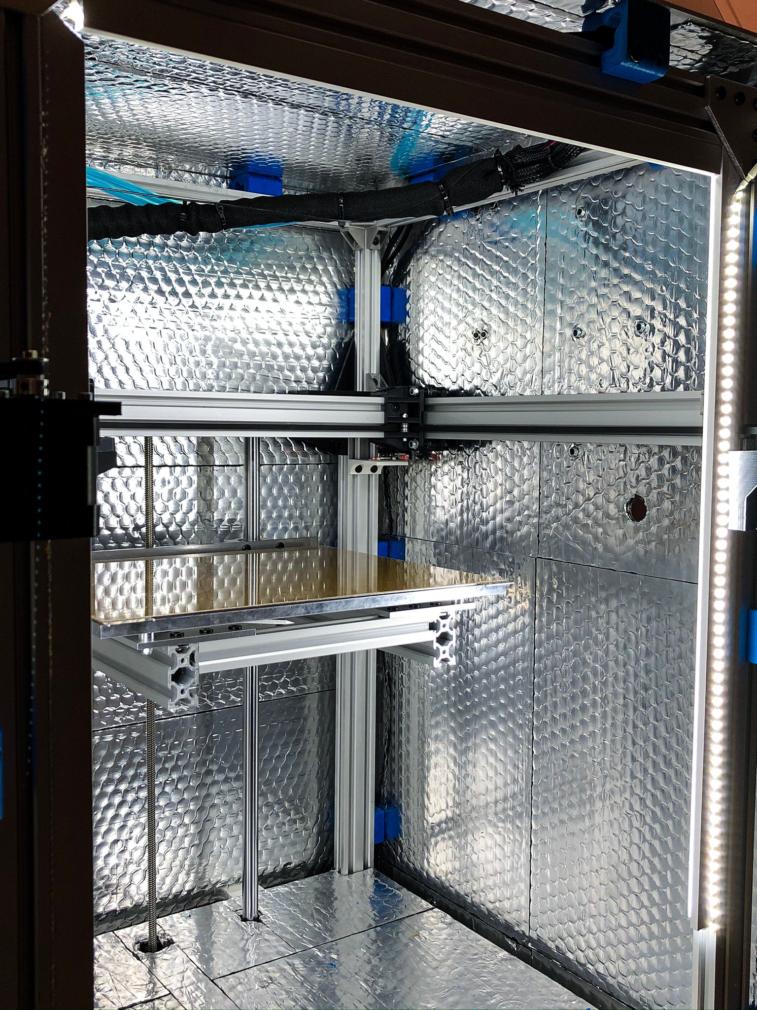
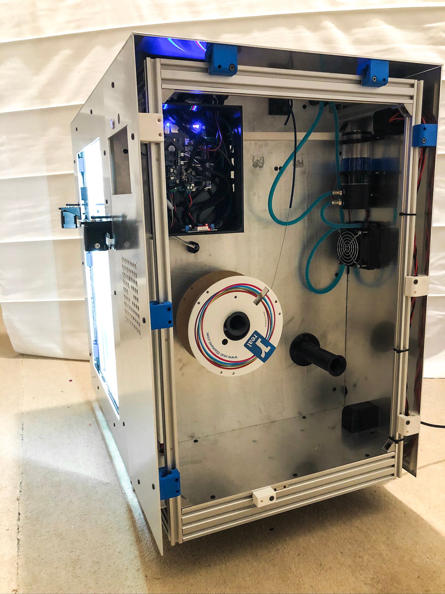
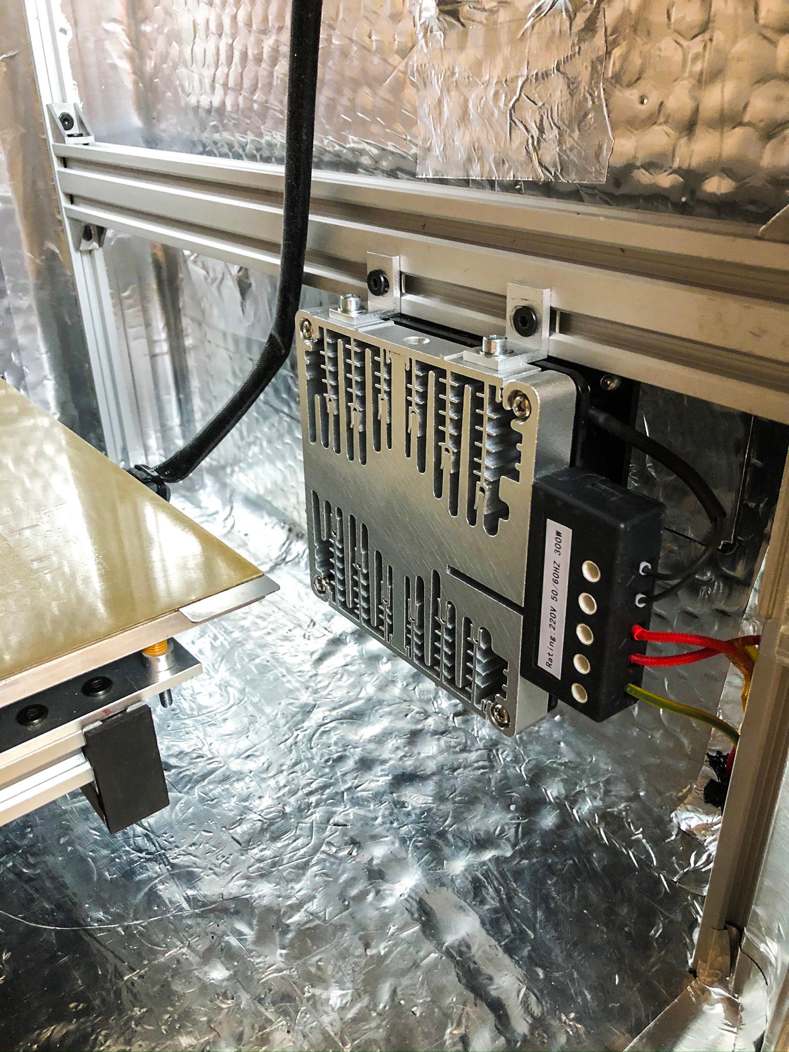
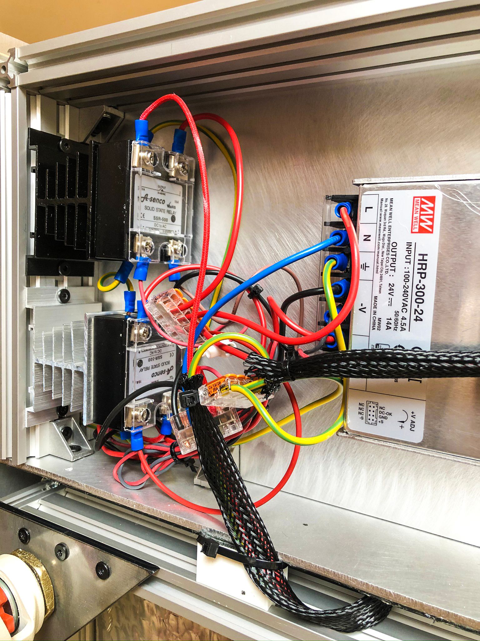
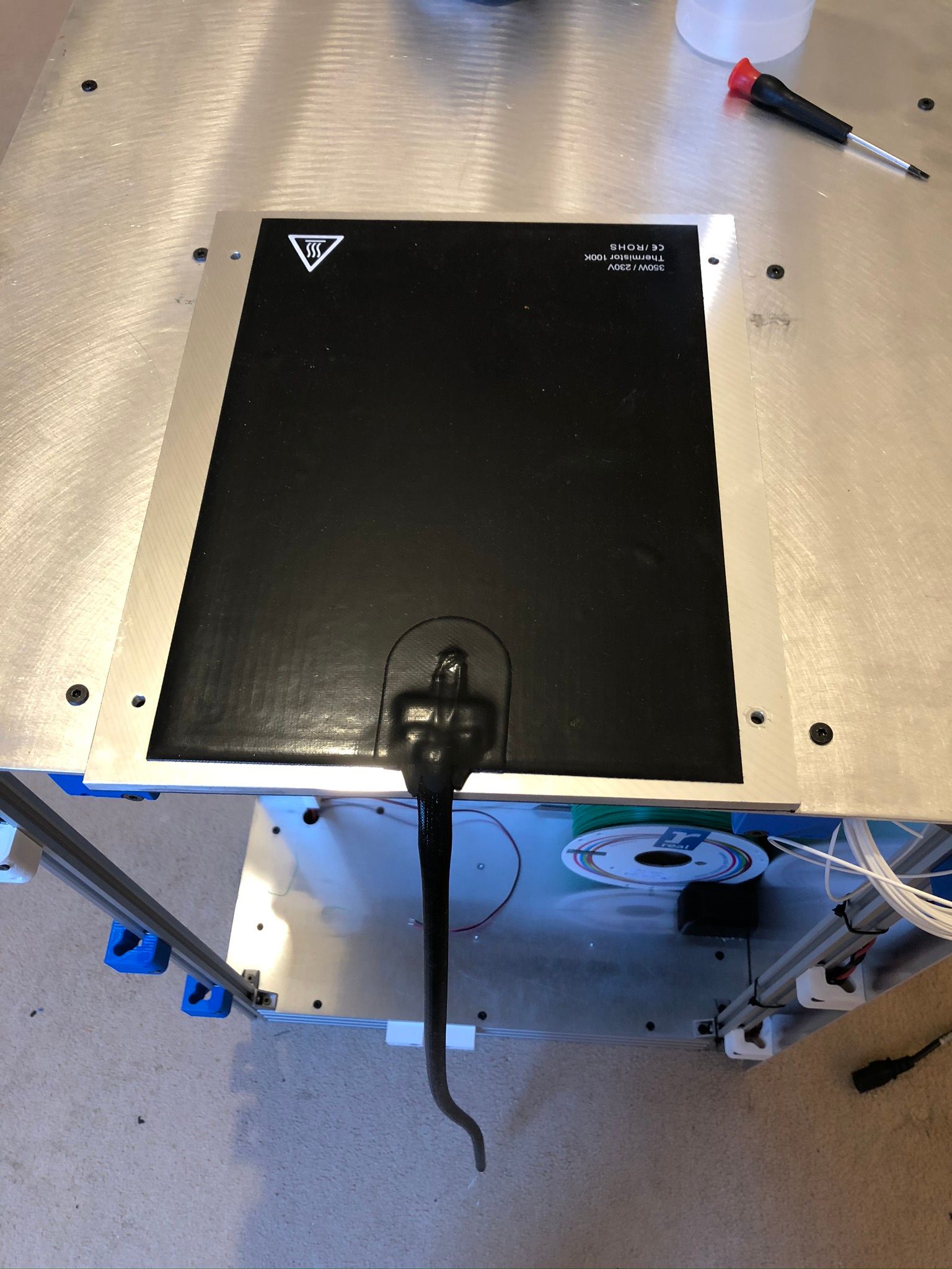
      • AC heated bed - 500W from Filafarm;
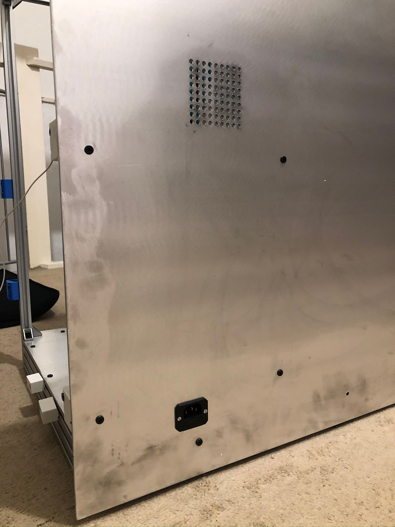
      • Charcoal filtration;
      • Hotend - 450C with PT100;
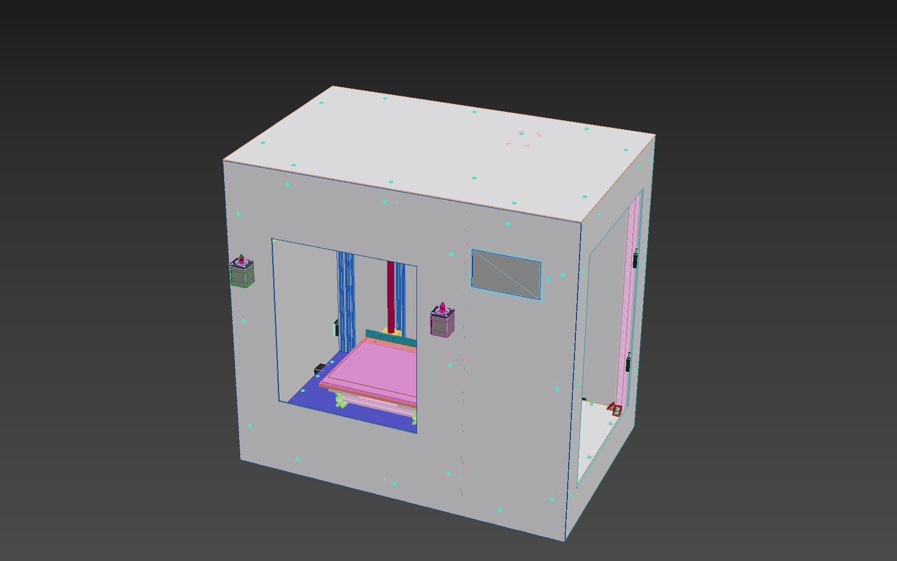
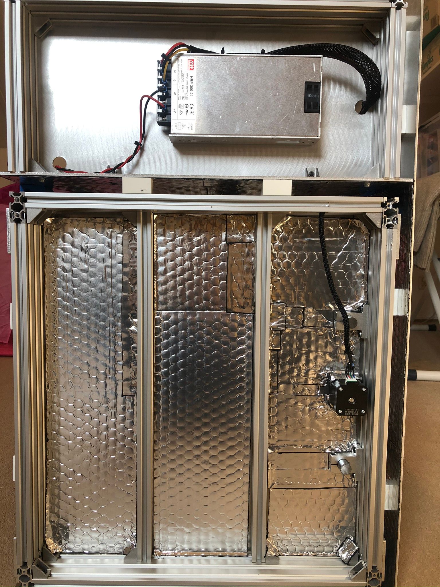
      • Fully enclosed machine with Electronic compartment and PanelDue 7";
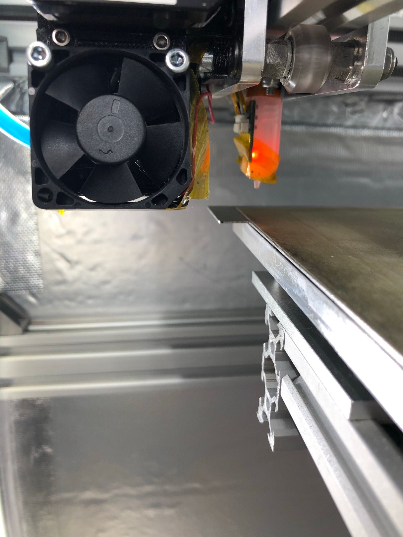
      • BL touch for now - later Metrol as they are rated 80C+;
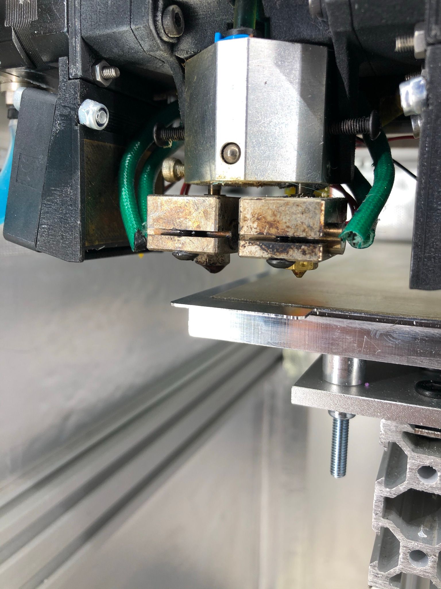
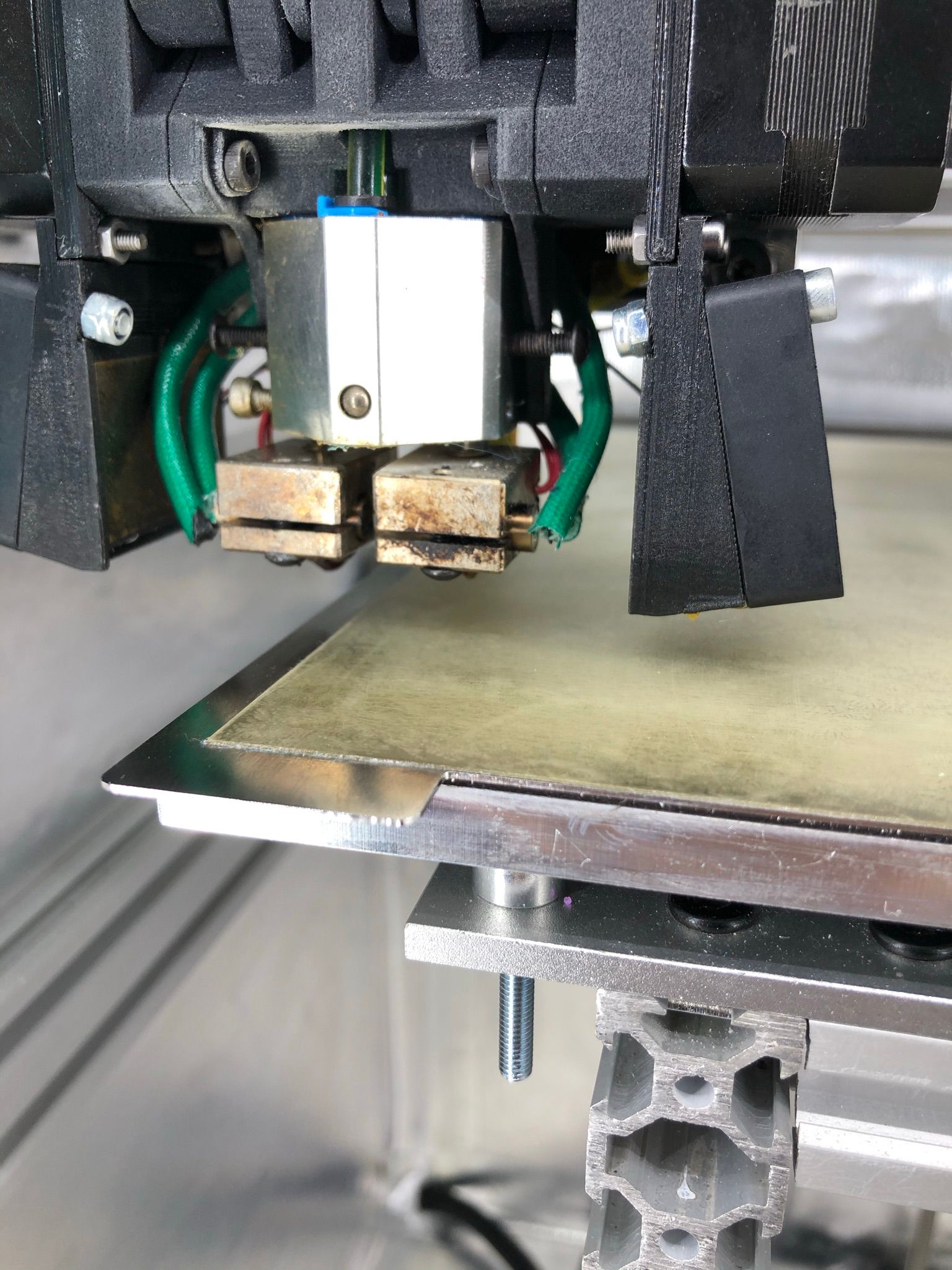
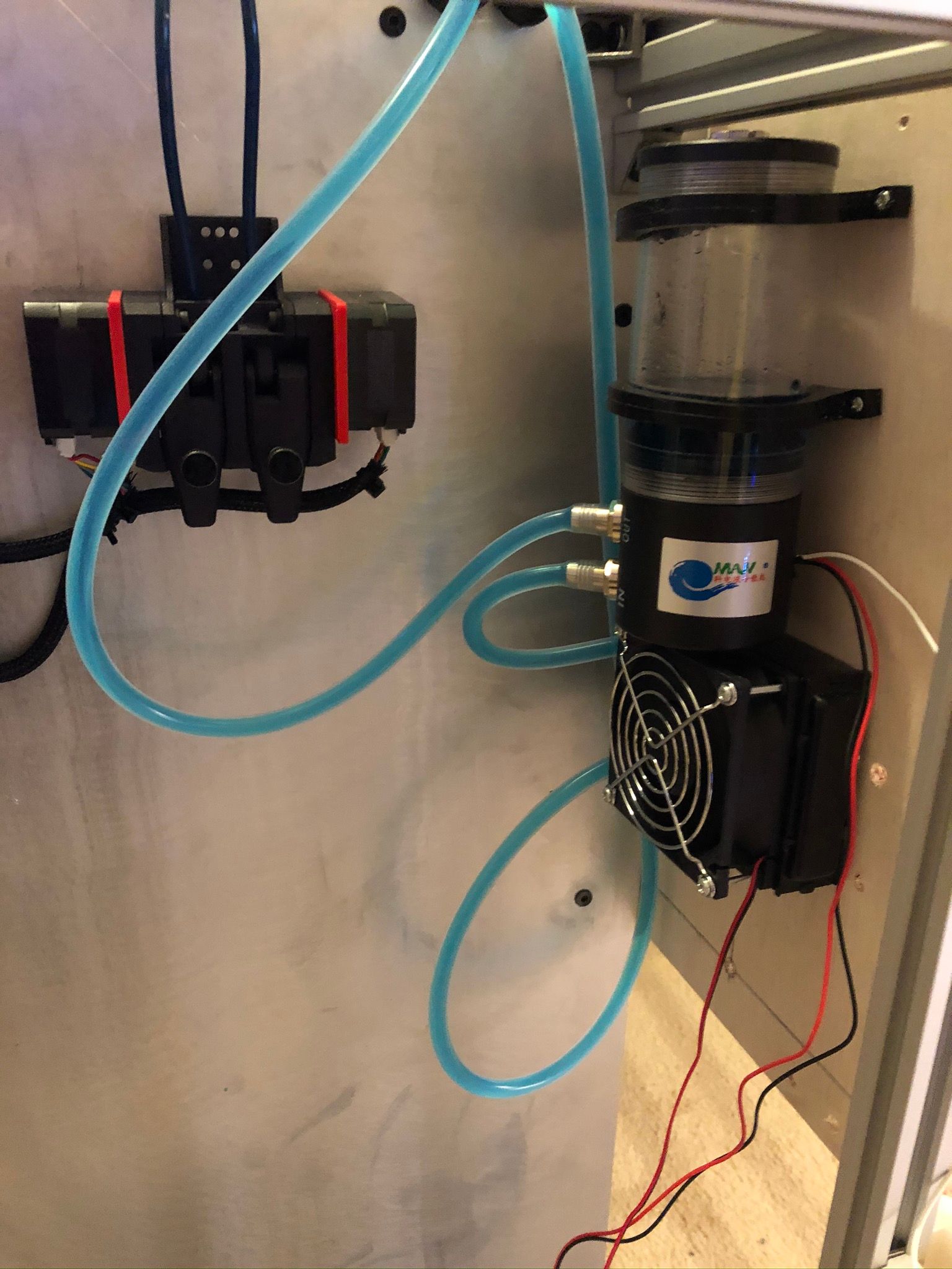
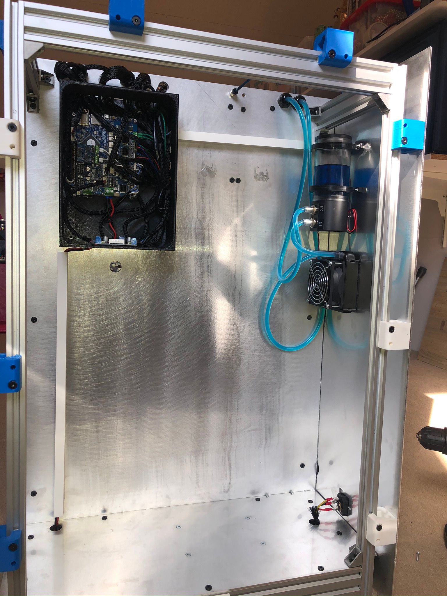
      • Water Cooled hot end - Chimera;
      • DuetWifi main electronic;
      • Dual Bondtech Extruders used as a Bowden became direct;
      • Able to print PEEK/PEI/PSU small objects of ~70x70x50mm;
      • Magnetic build plate from Filafarm with Filaprint surface;
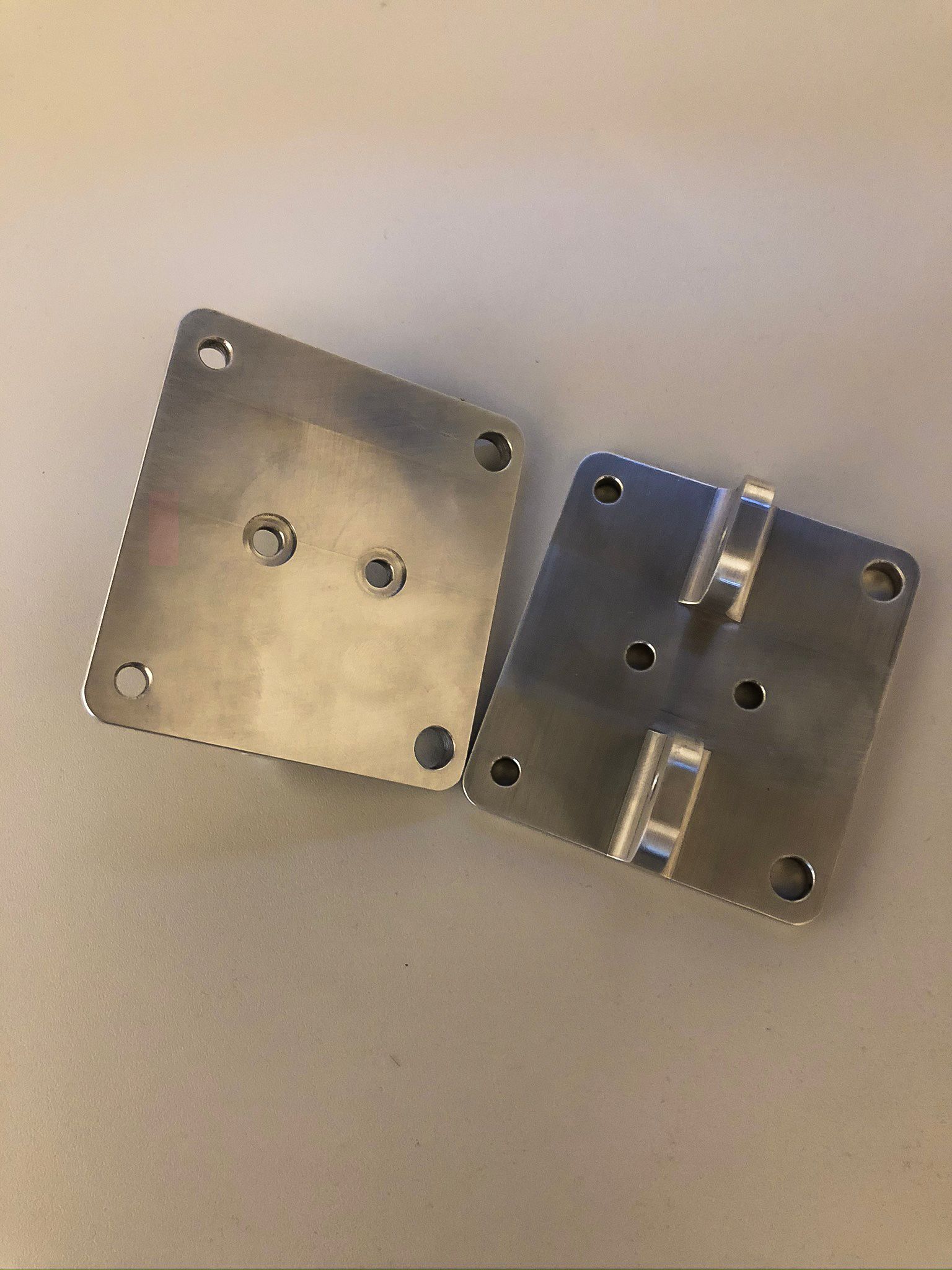
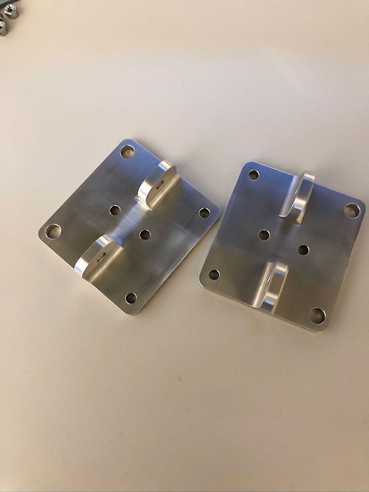
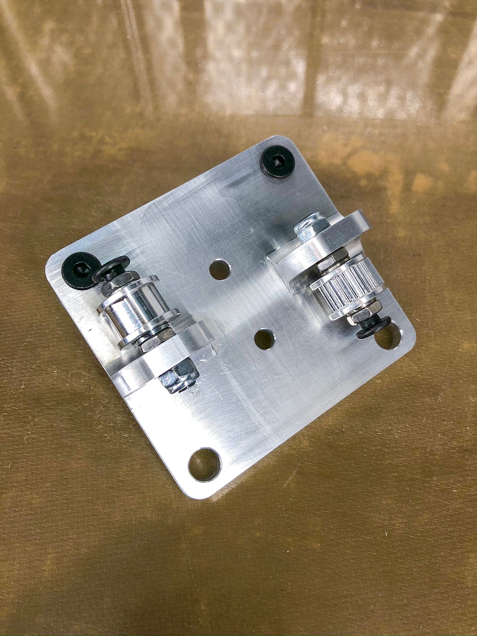
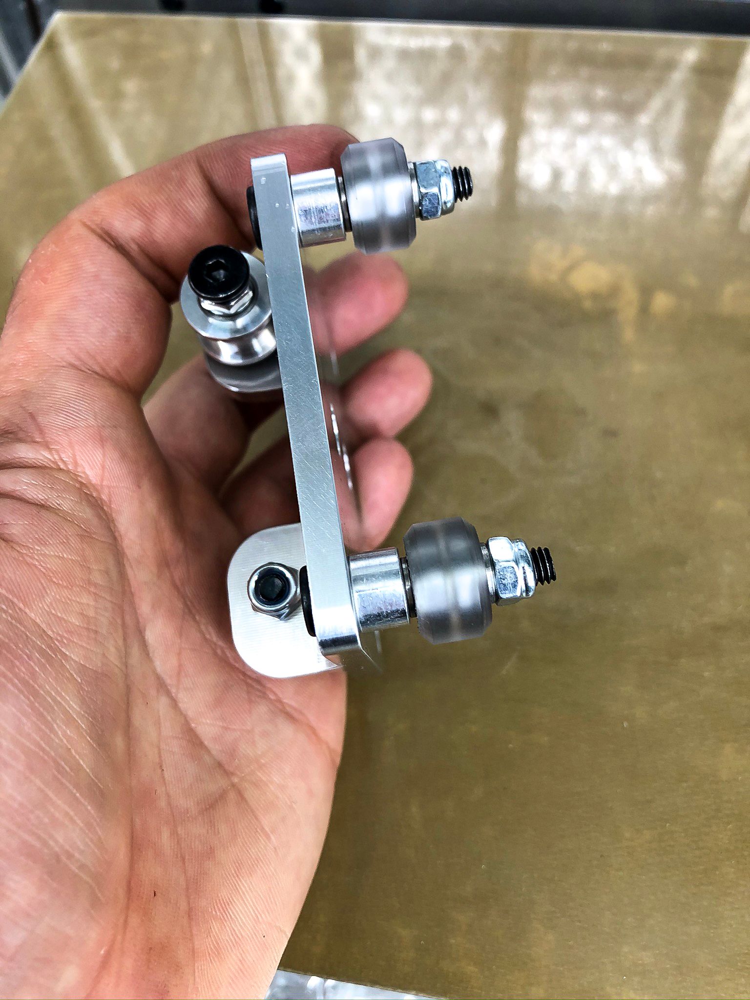
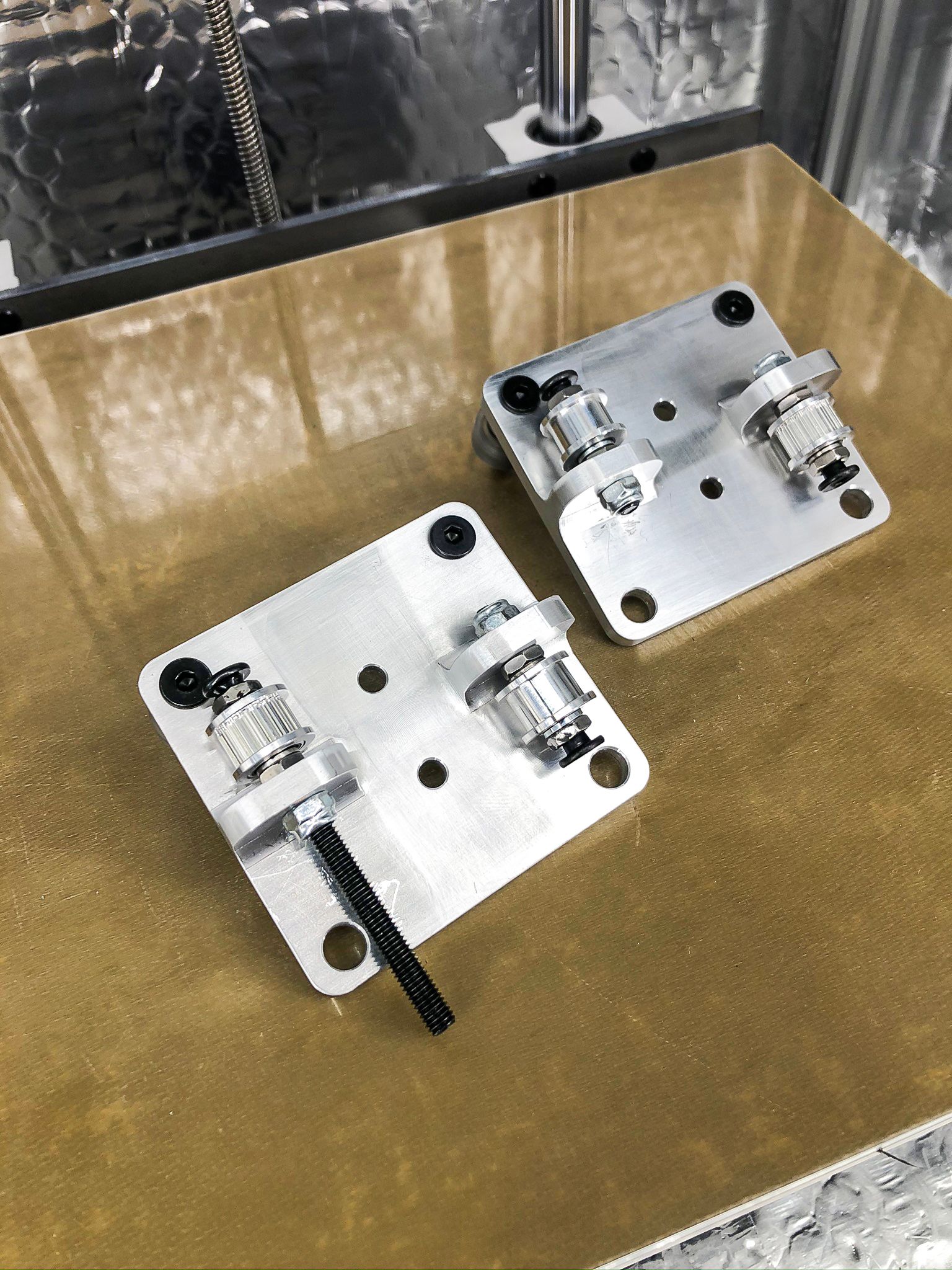
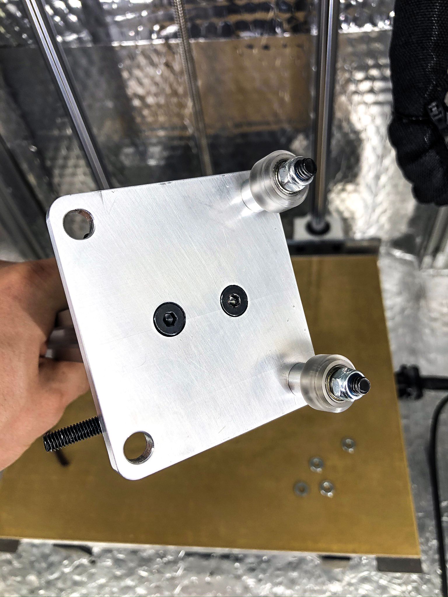
      • All printed parts would be replaced with milled Aluminium, I am already close to this stage as I am happy how everything working out so I can continue without worries 🙂

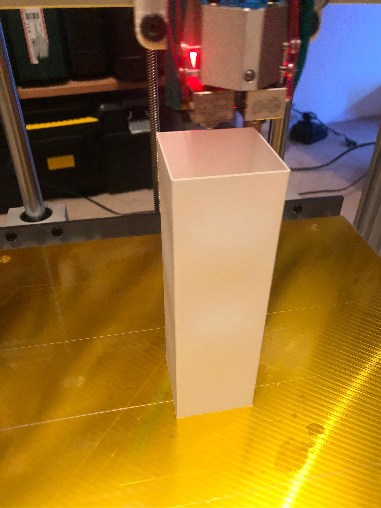
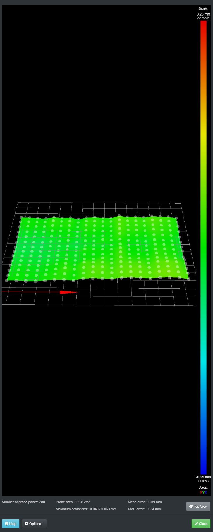
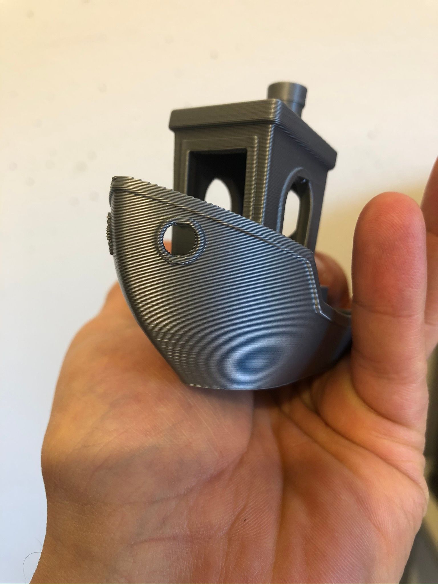
      The whole build itself comes out fairly aligned from the beginning, minor tweaks required to achieve 100x100mm cube printed with 100.06x100.04mm - which is sufficient I think.

      What is left to think about:

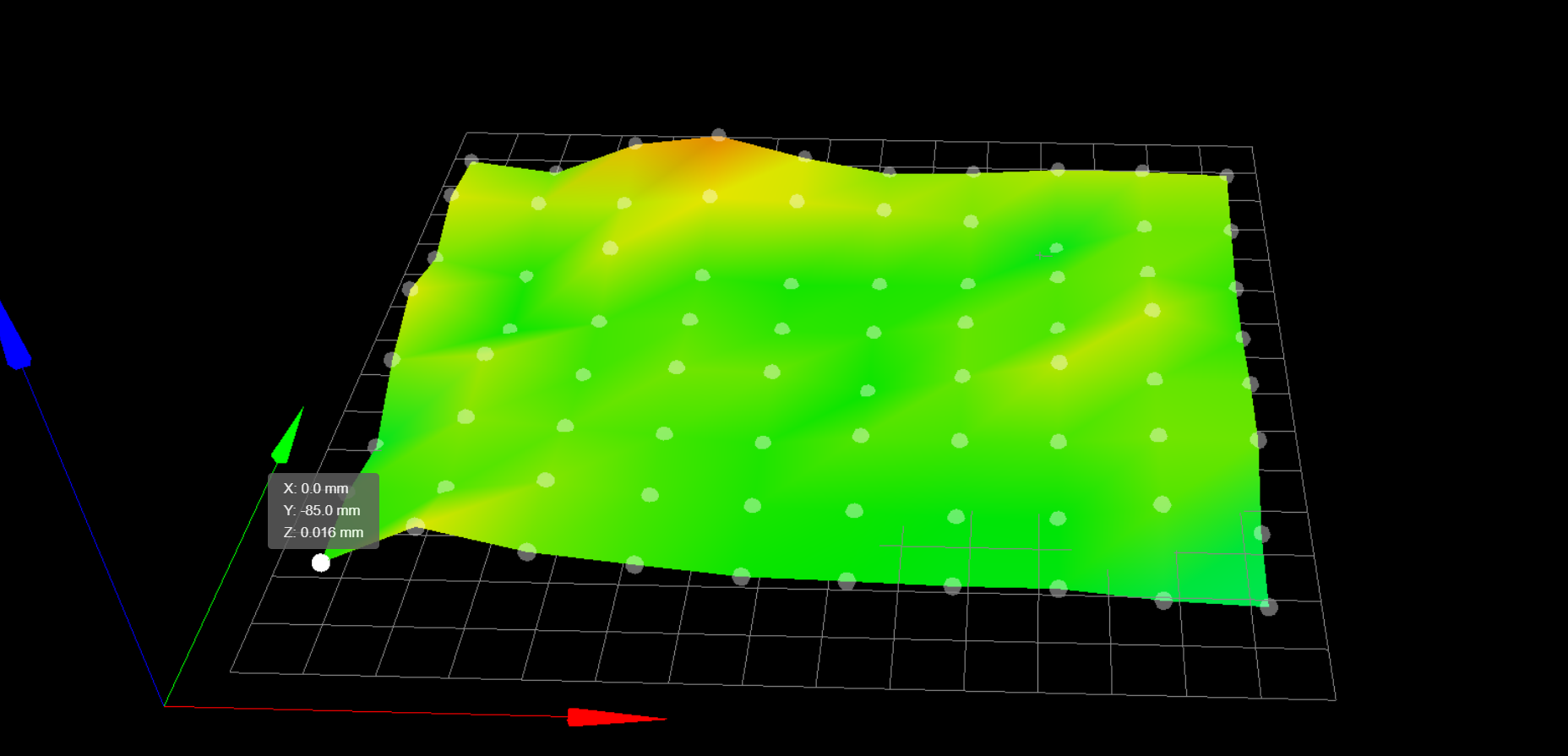
      My bed is fairly plane and BL touch does a great job I can print around the whole bed with a consistent width. What worrying me is it would be the same with a bigger object which has more weight 1kg+? I do have 16mm rods and 8mm trapezium lead screw, would it be better to put 12mm trapezium lead screw, or I am losing resolution this way?

      The filtration system, how to heat a chamber and control temperature, would it be enough 70C for PEI/PEEK/PSU. I saw a thread on ultimaker forum that somebody able to print those filaments with a 60C air temperature, small objects.

      Dual extrusion doesn't really work as I expected - maybe my tool change files should be adjusted properly. But it does leak then it switching tool then it goes to continue print - but I think this is just spending more time on tweaking feed rates and pressure advance.

      Still figuring out how to properly make a sealed front door.

      Capture1.JPG Capture.JPG

      IMG_5799.JPEG IMG_5790.JPEG IMG_5766.JPEG IMG_5217.JPEG

      More images here:
      (https://share.icloud.com/photos/0B3qJiJsvmaQ44aGGL3YA_zAw)
      -feel free to always check it as it will update with new images as I have new stuff to share 🙂

      If somebody has critics or comments please share knowledge and experience!

      posted in My Duet controlled machine
      felt342undefined
      felt342
    • RE: High-Temp E3D Fan

      Check this one -
      https://nl.rs-online.com/web/p/axial-fans/1442034/
      they do have -20 - 75C operating range.

      posted in General Discussion
      felt342undefined
      felt342
    • RE: Trying to remove tiny holes/gaps on layers...

      @skezo Is it only happen with PETG? Could be it has too much moisture in it?

      posted in Tuning and tweaking
      felt342undefined
      felt342
    • RE: WIP CoreXY with heated chamber

      Update - quick wrapping in aluminum foil. Hopefully I don't need to open it any soon 😄

      IMG_6350.jpeg IMG_6360.jpeg

      posted in My Duet controlled machine
      felt342undefined
      felt342
    • RE: WIP CoreXY with heated chamber

      And there is lighting, and top covered. Still waiting for a heated bed to come... 😐

      IMG_6350.JPEG
      IMG_6351.JPEG IMG_6352.JPEG IMG_6353.JPEG IMG_6355.JPEG

      posted in My Duet controlled machine
      felt342undefined
      felt342
    • RE: WIP CoreXY with heated chamber

      Hi all, things moving but very slow, this is progress so far by today. I got all-aluminum machined parts for the motion system, very happy with them, and moving very smoothly. I can tighten them very hard without worry what plastic will crack, or they will start wobble then the chamber is getting 45 degrees C. Besides this I also installed front panel and wheel to be able moving printer around as its getting quite heavy. Working on the door now and decided what it will be not hinged, but removable on the channel magnets, with transparent polycarbonate sheet.

      Some images:

      IMG_6722.JPEG
      IMG_6723.JPEG
      IMG_6726.JPEG
      IMG_6725.JPEG
      IMG_6727.JPEG
      IMG_6728.JPEG
      IMG_6730.JPEG
      IMG_6731.JPEG
      IMG_6735.JPEG
      IMG_6743.JPEG
      IMG_6745.JPEG
      IMG_6819.JPEG
      IMG_6824.JPEG
      IMG_6828.JPEG
      Capture.JPG
      Capture_latest-03.JPG

      posted in My Duet controlled machine
      felt342undefined
      felt342
    • RE: WIP CoreXY with heated chamber

      Okay, there I have a couple of new updates. I`ve been working on a heated chamber solution and found this one - https://szxinruite.en.made-in-china.com/product/vykEjoYlrwhx/China-Rhw-032-Industrial-PTC-Fan-Heater-for-Electric-Cabinet-with-UL-Thermostat-Heater-Temperature-Control-Heater.html

      I did order 300W version, and it gives me a 55C evenly distributed heat chamber in 15 minutes also with enabled heated bed set to 75 degrees for printing ABS, which gives me zero warp with abs and no distorted first couple of 5mm due to set low bed temperature.
      However as my plan was to get to 70C, I am thinking to order another same heater but rated to 600W or 800W and install it on the opposite wall and maybe on a bit different height. And hopefully, it will give me a reasonable speed till 70C.

      The nice feature of this heater is what it has integrated Temperature safety cut-out if the fan will die. The fan and fan casing made completely from steel.

      And a small esthetic addition to Z-axis, please see pictures! And I need to tide up the wiring here 🙂
      Till next time!

      IMG_7158.jpeg IMG_7160.jpeg IMG_7155.jpeg IMG_7093.jpeg IMG_7092.jpeg IMG_7091.jpeg IMG_7157.jpeg

      posted in My Duet controlled machine
      felt342undefined
      felt342
    • RE: WIP CoreXY with heated chamber

      Some updates on work in progress machine 🙂
      IMG_6333.JPEG IMG_6332.JPEG IMG_6331.JPEG IMG_6330.JPEG IMG_6325.JPEG IMG_6320.JPEG

      At this moment I am - working on lighting, sealing the chamber with aluminum foil, figuring out the door mechanism, wheels, and feet! Eventually, it became direct drive extruder, much happier with results!
      https://www.icloud.com/photos/#07fyEOQcG_z7WxKabaN22UowA

      posted in My Duet controlled machine
      felt342undefined
      felt342
    • RE: WIP CoreXY with heated chamber

      @mrehorstdmd

      Thank you!
      Yes indeed it looks like it might, but I moved it to the right so it does not interfere. In the end, I will remove it, otherwise, the cable hose and liquid hose will be in touch with top cover and probably will mount cable chain.
      The big thing I want to mount and test is a heated bed, but with this world situation of Corona I am already in a delay of 3 months...

      There is my latest benchy 🙂
      IMG_6339.JPEG IMG_6338.JPEG

      posted in My Duet controlled machine
      felt342undefined
      felt342
    • RE: WIP CoreXY with heated chamber

      And finally I got a bed heater! I am working now on a way to constrain the cable from the bed and installing TCO for safety. Overall I am very happy with this bed its get to 140C in 15 minutes and its only 350W on 8mm mic6 plate.
      IMG_6375.jpeg
      C54AA61C-C7BE-4DD3-9A4B-4373BC513027.jpeg 077-671d0cf8-066a-46e8-9c76-5b216a9b77ed-resized.jpeg)
      83C5C51A-192F-480D-8695-0A26881FD76E.jpeg

      posted in My Duet controlled machine
      felt342undefined
      felt342

    Latest posts made by felt342

    • RE: BL touch and how to define area for mesh compensation properly

      @o_lampe

      Thank you.
      Meaning what I should stick to this setting to make it right? Which locate the nozzle on top of 0,0 origin when it starts probe.

      ; Axis Limits
      M208 X-20 Y0 Z0 S1                                ; set axis minima
      M208 X321 Y208 Z305 S0                        ; set axis maxima
      ; Z-Probe
      G31 P25 X0 Y-47.06 Z2.150               ; set Z probe trigger value, offset and trigger height (positive value brings bed closer)
      M557 X-6:290 Y-47:150 S30                      ; define mesh grid
       
      
      posted in Tuning and tweaking
      felt342undefined
      felt342
    • RE: BL touch and how to define area for mesh compensation properly

      @phaedrux

      That is correct my nozzle is offset 47 mm from BL touch.

      With these settings I am getting BL touch measurement when nozzle is located on top of 0,0 origin. But in that case BL touch is measuring 47 mm in front which I think is not very accurate representation of the mesh.

      ; Axis Limits
      M208 X-20 Y0 Z0 S1                                ; set axis minima
      M208 X321 Y208 Z305 S0                        ; set axis maxima
      
      ; Z-Probe
      G31 P25 X0 Y-47.06 Z2.150               ; set Z probe trigger value, offset and trigger height (positive value brings bed closer)
      M557 X-6:290 Y-47:150 S30                      ; define mesh grid


      IMG_9215.JPEG

      ======================================================================================================================

      With these settings I am getting BL touch measurement when nozzle is moving to Y47mm. In that case BL touch is measuring at 47+47=Y94 coordinates... which is not good.

      ; Axis Limits
      M208 X-20 Y0 Z0 S1                                ; set axis minima
      M208 X321 Y208 Z305 S0                        ; set axis maxima
      
      ; Z-Probe
      G31 P25 X0 Y-47.06 Z2.150               ; set Z probe trigger value, offset and trigger height (positive value brings bed closer)
      M557 X-6:290 Y0:150 S30                      ; define mesh grid


      IMG_9217.JPEG

      ======================================================================================================================

      With these settings I am getting BL touch measurement when the nozzle is located 47 mm in front of the bed (in the air). In that case BL touch is measuring at 0,0 coordinates which I think is right but will it be an accurate representation for the nozzle. Or it will mean what the whole bed mesh will be shifted 47 mm and when nozzle will start print at 0,0 it will use mesh compensation for this point shifted by 47 mm in a mesh?

      ; Axis Limits
      M208 X-20 Y-85 Z0 S1                                ; set axis minima
      M208 X321 Y208 Z305 S0                        ; set axis maxima
      
      ; Z-Probe
      G31 P25 X0 Y-47.06 Z2.150               ; set Z probe trigger value, offset and trigger height (positive value brings bed closer)
      M557 X-6:290 Y-85:150 S30                      ; define mesh grid


      IMG_9220.jpeg

      I hope it is clearer now more or less 🙂

      Moving BL touch closer to the nozzle will do the trick probably what I want, but I don't want to move BL touch so close to the nozzle or any heat as it's already in harsh environment as my heated chamber goes to 80 degrees...

      posted in Tuning and tweaking
      felt342undefined
      felt342
    • BL touch and how to define area for mesh compensation properly

      Hi guys,

      Can somebody explain to me please how to set properly area for mesh compensation.

      This is how is set now, you can see what my left bottom point is -85 mm, made especially so my BL touch will measure the edge of build plate. It has set offset in Y direction from nozzle of Y-47.06.

      And this is my mesh grid coordinates defined.

      M557 X0:295 Y-85:150 S30                      ; define mesh grid
      

      Plus my axis limits:

      ; Axis Limits
      M208 X-16 Y-45 Z0 S1                          ; set axis minima
      M208 X321 Y208 Z305 S0                        ; set axis maxima
      

      022cf9a5-7e36-47e4-aa30-59233001c24a-image.png

      My concern here is if my nozzle is actually compensating at the right location if I look on to Y-85 in my first point. I do have feeling what the whole bed should be moved back by 85 mm on Y, to correctly represent compensation underneath the nozzle. I am not sure if I gave a clear issue here, but maybe somebody with more experience sees the issue here?

      There is my main files:

      ; Configuration file for Duet WiFi (firmware version 2.03)
      ; executed by the firmware on start-up
      ;
      ; generated by RepRapFirmware Configuration Tool v2.1.4 on Thu Jan 02 2020 22:17:48 GMT+0100 (Central European Standard Time)
      
      ; General preferences
      G90                                             ; send absolute coordinates...
      M83                                             ; ...but relative extruder moves
      M550 P"own"                                     ; set printer name
      
      M667 S1                                         ; select CoreXY mode
      
      ; Network
      M552 S1                                         ; enable network
      M586 P0 S1                                      ; enable HTTP
      M586 P1 S0                                      ; disable FTP
      M586 P2 S0                                      ; disable Telnet
      
      ; Drives
      M569 P0 R-1
      M569 P0 S1                                      ; physical drive 0 goes forwards
      M569 P1 S1                                      ; physical drive 1 goes forwards
      M569 P2 S1                                      ; physical drive 2 goes forwards
      M569 P3 S1                                      ; physical drive 3 goes backwards
      M569 P4 S1                                      ; physical drive 4 goes forwards
      M584 X4 Y1 Z2 E3:0                             ; set drive mapping
      M350 X16 Y16 Z16 E16:16 I1                      ; configure microstepping with interpolation
      M92 X200.8 Y200.8 Z400 E415:415			; set steps per mm
      M566 X500 Y500 Z20 E1500.00:1500.00      	; set maximum instantaneous speed changes (mm/min)
      M203 X15000 Y15000.00 Z600 E13000.00:13000.00   ; set maximum speeds (mm/min)
      M201 X4000 Y4000 Z100 E8000.00:8000.00      	; set accelerations (mm/s^2)
      M204 P1000 T1000				; printing acceleration
      M906 X1300 Y1300 Z1500 E600:600 I30             ; set motor currents (mA) and motor idle factor in per cent
      M84 S90                                         ; Set idle timeout
      
      ; Axis Limits
      M208 X-16 Y-45 Z0 S1                                ; set axis minima
      M208 X321 Y208 Z305 S0                        ; set axis maxima
      
      ; Endstops
      M574 Z1 S2                		     ; set active low and disabled endstops
      M574 X1 S0                			  ; set active high endstops
      M574 Y2 S0
      
      ; Z-Probe
      M307 H3 A-1 C-1 D-1                             ; disable heater on PWM channel for BLTouch
      M558 A10 S0.01 P9 H3 F60 T5000 R0.3                          ; set Z probe type to bltouch and the dive height + speeds
      G31 P25 X0 Y-47.06 Z2.150               ; set Z probe trigger value, offset and trigger height (positive value brings bed closer)
      M557 X0:295 Y-85:150 S30                      ; define mesh grid
      
      ; Heaters
      M141 H5 					; heater 5 is the chamber heater
      M305 X1 P5 B4725 C7.060000e-8 			; heater 5 is monitored by a E3D thermistor
      ;M307 H5 C99000 D0.05 S1.00 V0.0 B0		; disable bang-bang control for the chamber heater
      M143 H5 S90
      ;M307 H0 B0 S1.00                        	; disable bang-bang mode for the bed heater and set PWM limit
      M305 P0 T100000 B4138 R4700             	; set thermistor + ADC parameters for heater 0
      M143 H0 S150                            	; set temperature limit for bed heater 0 to 150C
      M305 P1 X200                                    ; configure PT100 for heater 1
      M143 H1 S480                                    ; set temperature limit for heater 1 to 480C
      M305 P2 X201                                    ; configure PT100 for heater 2
      M143 H2 S300                                    ; set temperature limit for heater 2 to 300C
      
      ; Fans
      M106 P0 S0 I0 F20 H-1                          ; set fan 0 value, PWM signal inversion and frequency. Thermostatic control is turned off
      M106 P1 S1 I0 F20 H-1                          ; set fan 1 value, PWM signal inversion and frequency. Thermostatic control is turned off
      M106 P2 S1 I0 F20 H-1                          ; set fan 2 value, PWM signal inversion and frequency. Thermostatic control is turned off
      
      ; Tools
      M563 P0 S"Left" D0 H1 F-1                       ; define tool 0
      G10 P0 X0 Y0 Z0                                 ; set tool 0 axis offsets
      G10 P0 S0 R175 									; Set tool 0 active and standby temperatures
      M563 P1 S"Right" D1 H2 F-1                      ; define tool 1
      G10 P1 X20.09 Y0 Z0                               ; set tool 1 axis offsets
      G10 P1 S0 R175 									; Set tool 0 active and standby temperatures
      
      ; Custom settings are not defined
      
      ; Miscellaneous
                                                 ; load saved parameters from non-volatile memory
      M501


      ; bed.g
      ; called to perform automatic bed compensation via G32
      ;
      ; generated by RepRapFirmware Configuration Tool v2.1.4 on Thu Jan 02 2020 22:17:48 GMT+0100 (Central European Standard Time)
      
      M561 ; clear any bed transform
      G29  ; probe the bed and enable compensation
      
      
      ; homeall.g
      ; called to home all axes
      
      ; Home XY for Z homing
      G91                     	; relative positioning
      M913 X50 Y50	 		; set X Y motors to 50% of their normal current for homing
      G1 S1 X-321 Y272.5 F4000   	; course home X or Y
      G1 S1 X-321 F4000              	; course home X
      G1 S1 Y272.5 F4000              	; course home Y
      G1 X2 Y-3 F4000             	; move away from the endstops
      G1 S1 X-321 F200           	; fine home X
      G1 S1 Y272.5 F200               	; fine home Y
      M913 X100 Y100	 		; set X Y motors to 100% of their normal current
      
      ; Z homing section follows
      G90				; absolute positioning
      G1 X146 Y106 F4000		; Move x and Y axis over to bed center so probe is on top of bed
      
      ; Probe the bed
      M558 A1 F600 ; Set single probing at faster feed rate
      G30 ; Do a single probe to quickly home Z axis
      M558 A10 F100	 ; Set multi probing at slower feed rate
      G30 ; Probe again to get a more accurate position			; Probe the bed
      
      ; Move X and Y back Home
      G1 X0 Y0
      
      posted in Tuning and tweaking
      felt342undefined
      felt342
    • RE: Enclosure heater on Duet 3

      I do use this type of heater - https://szxinruite.en.made-in-china.com/product/vykEjoYlrwhx/China-Rhw-032-Industrial-PTC-Fan-Heater-for-Electric-Cabinet-with-UL-Thermostat-Heater-Temperature-Control-Heater.html

      At first, I've been using a 300W version which gives me 55C in 15 minutes with a heated bed set to 75. Now I do have installed 800W + 300W and together they are reaching 70C in 15 mins without a heated bed.

      However, during heating, they turn off then the surface area of the radiator reaching specific temp. I am planning to mount the fan directly on the wall and make a-holes in the sidewall to suck cold air from outside and heat it through the radiator. Which I hope will keep the them on for a longer period and will heat even faster.

      https://forum.duet3d.com/topic/13873/wip-corexy-with-heated-chamber/67?_=1598174589336

      posted in Duet Hardware and wiring
      felt342undefined
      felt342
    • RE: WIP CoreXY with heated chamber

      @Baenwort

      Hi I don't know the official type actually, I had a facility next to my house, and those guys were specialized on heating systems. They suggest me this foil - it is blend of resin and glass fiber and gives you deadening effect because of resin plus prevent heat transfer because of fibre glass. Similar what is used in a car for deadening wall to prevent vibrations and noise but there is without glass fibre. I got a pieces from them which they are throwing away 🙂 Works good!

      posted in My Duet controlled machine
      felt342undefined
      felt342
    • RE: WIP CoreXY with heated chamber

      Okay, there I have a couple of new updates. I`ve been working on a heated chamber solution and found this one - https://szxinruite.en.made-in-china.com/product/vykEjoYlrwhx/China-Rhw-032-Industrial-PTC-Fan-Heater-for-Electric-Cabinet-with-UL-Thermostat-Heater-Temperature-Control-Heater.html

      I did order 300W version, and it gives me a 55C evenly distributed heat chamber in 15 minutes also with enabled heated bed set to 75 degrees for printing ABS, which gives me zero warp with abs and no distorted first couple of 5mm due to set low bed temperature.
      However as my plan was to get to 70C, I am thinking to order another same heater but rated to 600W or 800W and install it on the opposite wall and maybe on a bit different height. And hopefully, it will give me a reasonable speed till 70C.

      The nice feature of this heater is what it has integrated Temperature safety cut-out if the fan will die. The fan and fan casing made completely from steel.

      And a small esthetic addition to Z-axis, please see pictures! And I need to tide up the wiring here 🙂
      Till next time!

      IMG_7158.jpeg IMG_7160.jpeg IMG_7155.jpeg IMG_7093.jpeg IMG_7092.jpeg IMG_7091.jpeg IMG_7157.jpeg

      posted in My Duet controlled machine
      felt342undefined
      felt342
    • RE: Setting up heater chamber - need help

      @JoergS5

      I must say it`s a nice way of solving the issue, digging the source code, will take it as a tip 🙂

      posted in Tuning and tweaking
      felt342undefined
      felt342
    • RE: Setting up heater chamber - need help

      @JoergS5

      That seems working without error!
      I didn't try negative D, but I set D to 1 and kept C at 2000, waiting for autotune and values 🙂

      Thanks a lot again!

      posted in Tuning and tweaking
      felt342undefined
      felt342
    • RE: Setting up heater chamber - need help

      @JoergS5

      Happens 🙂
      Thank you!

      posted in Tuning and tweaking
      felt342undefined
      felt342
    • RE: Setting up heater chamber - need help

      @JoergS5

      Yeah, I really appreciate your help and digging in! What I am thinking is maybe better to move thermistor to the middle of the chamber, it will probably be the faster response until I have only one heater.

      posted in Tuning and tweaking
      felt342undefined
      felt342