Anybody wants a stepper motor analyzer?
-
@zapta
Thanks for the input! I was thinking about a voltage divider too. That should be extremely easy to compensate for. About the output voltage, I've yet to find how high it goes (shouldn't be more than 4V if we consider the 350mV/A range plus the offset).The main idea behind this adaptation is to use it above the +/-2.5A range on Nema23 and over. +/-3A would be acceptable but not ideal. I perfectly agree on tackling the 5V issue first. I'm quite sure a divider would work fine with the relatively high frequency of the signal, but insight on that would be much appreciated.
I'm still unsure if the firmware is as easy to adapt as you say. Plus, now that you pointed out, I'll probably keep the 2.5A scale.
Thanks for the help and I'll update you with the schematics
-
@zapta Slight change of plans: I found the same sensor, but that works on 3.3V. It's still ±5A, with a lower resolution (230mV/A compared to 350mV/A). It has a lower offset (1.5V) and the full range can be read by the Pico's 3.3V I/O. https://www.mouser.it/ProductDetail/ACEINNA/MCA1101-5-3?qs=PzGy0jfpSMs%252BNw%2FnqBFIdA%3D%3D
It's (theoretically speaking and pinout aside) a direct replacement for the ACS70331. My question now is: firmware-wise, what do I have to adjust? If I understand this correctly, I just have to adapt
//static const SensorSpec GMR_2P5_SENSOR("G2P5A", 2500, 0.4)
to suit my specs
//static const SensorSpec GMR_2P5_SENSOR("G2P5A", 5000, 0.23);.
Should I also uncomment//constexpr int kMaxMilliamps = 2500;and set it to 5000 to read the full scale?
For now, I'm just thinking about the analyzer changes, UI and graphs axis can be adjusted later.
Also, what about the offset? It's the same as the ACS70331, so we should be alright?
Thanks in advance for your time and patience. I really like the project and I want to keep it alive.
Cheers! -
@keybored, I would suggest to start with just changing 0.4 to 0.23 and run it as is. The Reset function in the setting page should take care of the different offset level.
Once that works, if you would like to increase the range (and decrease the screen sensitivity which I am not sure is useful for most 'normal' stepper motors), you can look into increasing the range. That would require adding in a few places additional Y scale definitions for 5000ma similar to this
-
@zapta Thanks! I'll change the board design and proceed on this track then. Do you think the lower sensing resolution will impact the quality of the readings?
-
@keybored, I don't expect the lower sensitivity to be significant.
Of course, I don't know for sure since I never used that IC.
-
I am trying now a new approach, a BLE Stepper Motor Analyzer. It still at an early stage, but so far looks feasible. Imagine a small widget, smaller than a matchbox, with 4 pass through stepper motor wires. The widget harvests a small amount of power from the wires (~100mw) to power a small microcontroller (Nordic NRF52832) that monitors stepper signals, extracts information such as steps/speed/waveforms, and sends it wirelessly via BLE to an app on a computer, smart phone, or even to a DWC plugin (which uses Web Bluetooth).
I don't know if it's all possible but initial tests look good. With a NRF52832 that samples two analog channels and sends the extracted data to a PC via bluetooth (max sampling rate I could get is 40Khz per channel compared to 100Khz on the Simple Stepper Analyzer). Power harvesting also looks feasible with a four phase full rectifier bridge, a small capacitor and a 5-30V -> 3.3 DC/DC converter. The energy is available as long as the stepper is energized, regardless if it moves or not and on what microstep/phase it happened to stop. Could also add a small battery rechargeable or not, if needed.
As for the client software, I am thinking of a reference python client that people can use to create desktop apps or as reference design for mobile and other clients.
As I said, it's still at an early phase and I don't know for certain that this is feasible.
Any thoughts?
-
@zapta I'll take five.
-
@oliof said in Anybody wants a stepper motor analyzer?:
@zapta I'll take five.
Will keep it in mind. My preference would be to provide it to a few developers that will build real apps (for desktop, mobile, or web bluetooth).
One challenge I hit is how to calibrate zero current if the MCU is not powered when the current is zero.
")
-
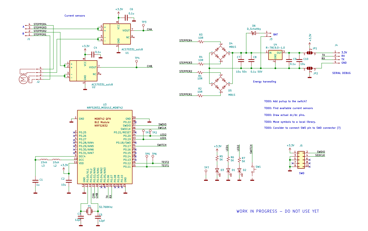
Had more progress with the BLE stepper probe and was able to display on a PC a real time step and speed graphs over BLE (using python/Bleak/Pyqtgraph and the PC side). Sill need to do some tests, e.g. of the energy harvesting, but it feels feasible. The MCU and the radio consumes about 3ma and the current sensors about 5ma each (all at 3.3v), for a total of ~40mw. This is the current schematic (not tested):
If anybody thinks that I am doing something terribly wrong (e.g. damaging the Duet's driver) now it's the time to speak
-
@zapta
I come from Hong Kong, I would like to order a PCB , how can I contact you and place a order? -
@rickykwongwm, PCB of what version, the one with touch screen or the experimental one with bluetooth?
-
@zapta
I prefer a set of PCB with touch screen, but experimental one only is also acceptable .
could u leave your contact to me with quotation ? -
I wonder if you have the stepper motor analyzer with touch screen. If you do, can you send me a quotation for the cost including shipping? I am from Winnipeg, Canada.
Yours sincerely,
Bruce Dewald. -
@brucedewald , sorry, I don't have any left. The goal of this project was to put a reference design in the public domain rather than actually producing them.
-
@brucedewald I still have some available from my original batch. If you're interested send me a direct message.
-
This post is deleted! -
@adamfilip I suggest you read the thread above
")
-
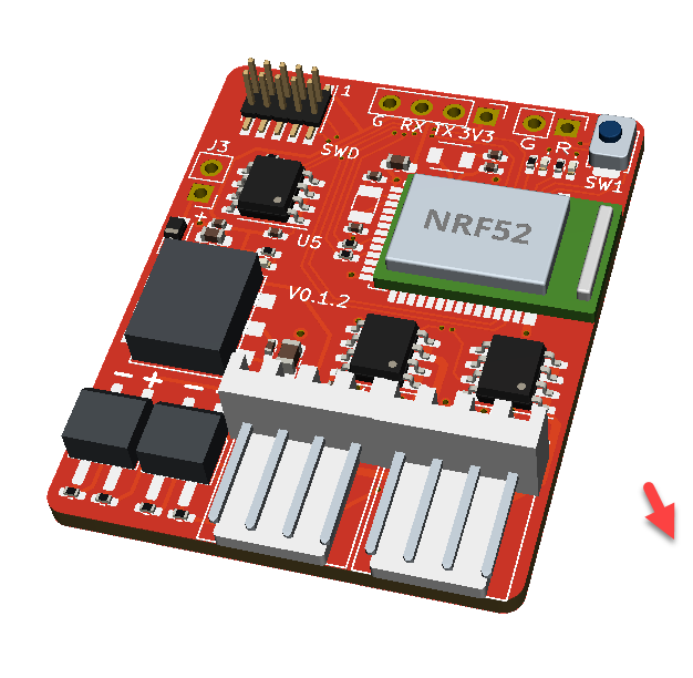
The second iteration of the Bluetooth version went out to JLCPCB. They install all the SMD parts except for the bluetooth module and the two current sensors. Still working on it but the core functionality already works. This version doesn't need external power, just connection to the stepper wires.
-
Hi.
I am planning to sell a small quantity of this analyzer in Japan for CNC users.
I found a cheap current sensor CC6920BSO-5A made in China at LCSC and tested it. LCSC Part No: #C2880430
This sensor also drive in 3.3V.
With this, the current sensor can also be mounted on the board in JLCPCB.I want to share you the test result.
There appears noises on the signal. But I think It is not a problem to get rough forms of waveform.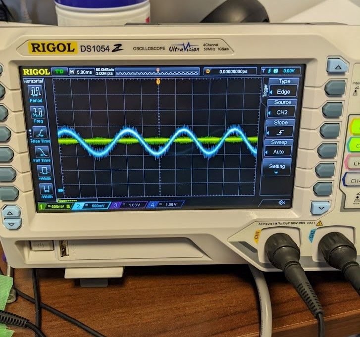

movies:
https://youtu.be/GVSU9TVF_7k
https://youtu.be/dTQMCF_6i5k -
@nyaru, that's very useful, especially the availability from JLCPCB. Thanks.
I have hard time downloading the datasheet from LCPCB. Do you happen to have it?
If the sensitivity of this chip is lower, e.g. 200mv/A instead of 400mv/A, it can be compensated in firmware.
Do CNC users typically need higher current range than 3D printers?
Edit: The firmware does basic signal filtering which reduces the impact of the noise. https://github.com/zapta/simple_stepper_motor_analyzer/blob/main/platformio/src/acquisition/analyzer.cpp#L323