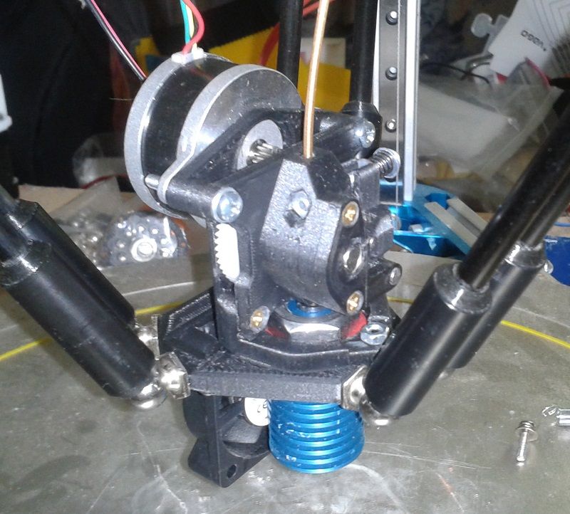
[Delta] Rod spacing 20mm, Pros & Cons?
-
@o_lampe the smaller your arm spacing (between parallel arms), the less stable your effector is: https://reprap.org/wiki/Delta_geometry#Effector_stability
In theory you want to spread the parallel arms as far from each other as possible, whilst putting the corner joints on top of each other (like the Smart Effector, and most delta designs out there).
Might be that you can get away with it though? There's only one way to find out...

-
@engikeneer said in [Delta] Rod spacing 20mm, Pros & Cons?:
the smaller your arm spacing (between parallel arms), the less stable your effector is
One user has made a spreadsheet to calculate that, but I can't find it back. @garyd9 IIRC it was you?
It also answered the question, if a wider effector has negative effects.I want to put the DD extruder as close to the effector as possible to avoid it being top heavy.
-
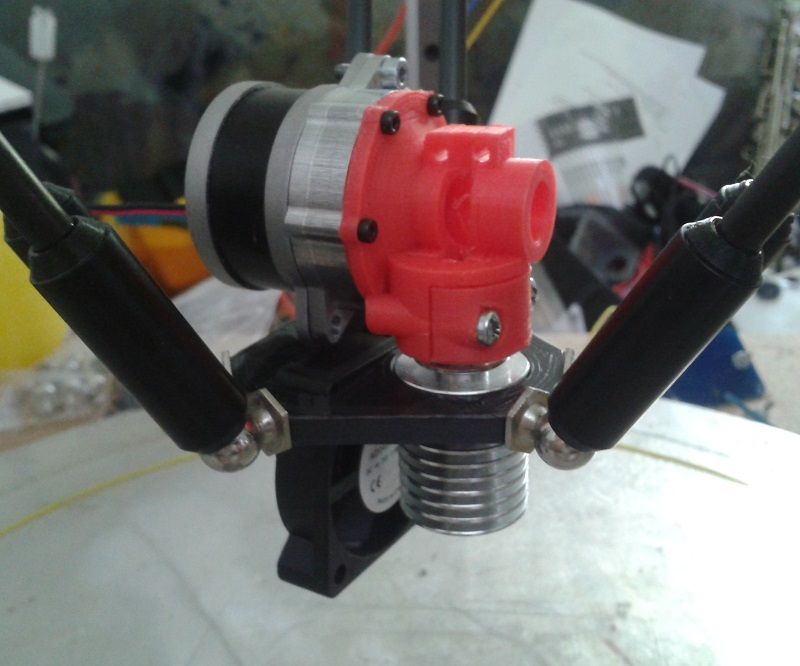
Have made a test-fit of the DD extruder all the way down to th effector.
It doesn't foul the rods at no place. Could even use a wider rod spacing, but 20mm is so tempting because of the mgn12 carriers.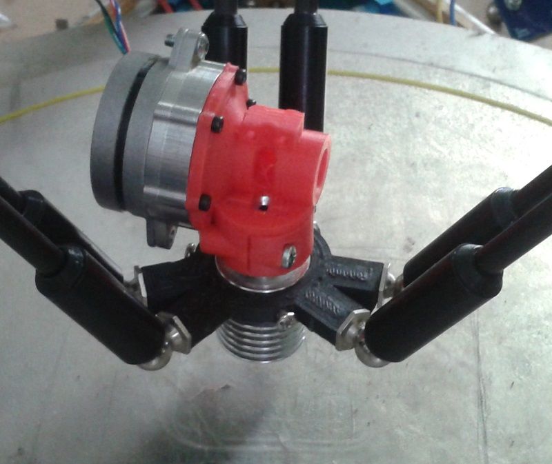
-
@o_lampe
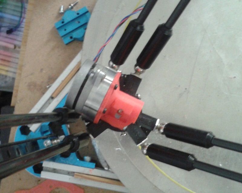
Now I can put fans and hotend below the effector to have a better CoG.
The effector I made has the usual 55mm spacing from the Smart Effector, but 20mm instead of 12mm between adjacent ballstuds.
It would be pretty easy to adapt, except mounting the heatsink is difficult. -
The bigger LDO-orbiter-style stepper also fits the bill.
I was wondering, how bad would it be to have the nozzle offcenter?
As you can see, there's a ~15mm gap between the exxtruder housing and the rods on therightleft. (the picture is flipped around)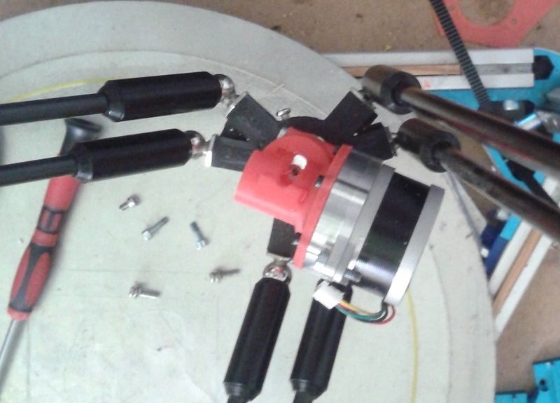
-
12mm nozzle offset, looks good and leaves room for a 40mm fan cutout.
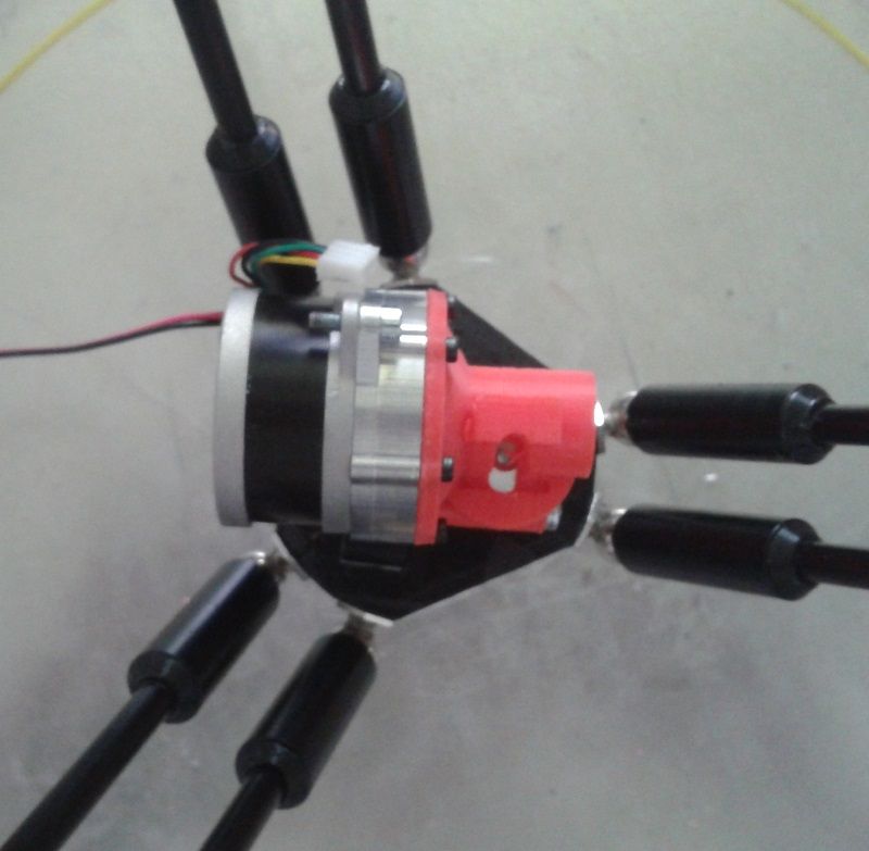
-
-
@o_lampe said in [Delta] Rod spacing 20mm, Pros & Cons?:
@engikeneer said in [Delta] Rod spacing 20mm, Pros & Cons?:
the smaller your arm spacing (between parallel arms), the less stable your effector is
One user has made a spreadsheet to calculate that, but I can't find it back. @garyd9 IIRC it was you?
It also answered the question, if a wider effector has negative effects.I want to put the DD extruder as close to the effector as possible to avoid it being top heavy.
(For some reason, the forum doesn't notify me whatsoever on mentioned, so I'm just now seeing this message...)
I didn't make a spreadsheet, per se, but used the theory posted in the reprap wiki to find the ratio's used by the smart effector, and carry that same ratio to any other arm spacing. It was in a "smart effector tool board" thread. I'll find it and edit this post...
Edit: it's around here (it's difficult to link to the single post on this forum): https://forum.duet3d.com/topic/19522/smart-effector-including-toolboard-capabilities/50
The relevant part is:
Also, there's more to arm spacing than just the gap between two parallels arms: there's also the gap between the "centers of articulation" (as described here: https://reprap.org/wiki/Delta_geometry#Effector_stability and referenced there as "b".) From that page, there's a theoretical relationship between effector stability, the arm spacing, and "b".
For reference, @dc42's smart effector has an arm spacing of 55mm, and a "b" of 12mm. Using the formula provided on that linked page (Tilt Effector Stability = (Arm space)²/b), the smart effector has a "TES" of ~252.08.
Assuming that theoretical work is accurate (or close to accurate), the effector from mrac1 has a much lower stability of ~134.94. (64^2 / 30.354)
From that, I started playing around in Fusion360 modeling arm spacing, and set thing up so that the "b" value is computed automatically based on the arm spacing in order to maintain a "TES" value of 252.08. (I just force the "b" value to be "( arm space )² / 252.08 mm.") Then I linked mrac1's excellent extruder model on top of the resulting sketch and kept adjusting the arm space until the arms (and arm movement) was completely clear of the lines connecting all 6 ball joints. (My choice of clearance was somewhat arbitrary. Some delta builds would need more space, and others would need less.)
-
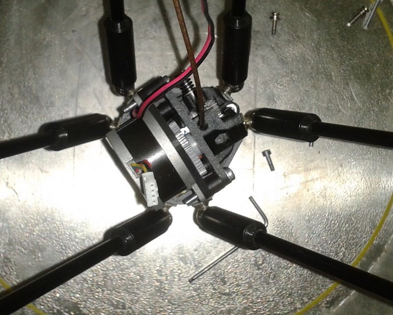
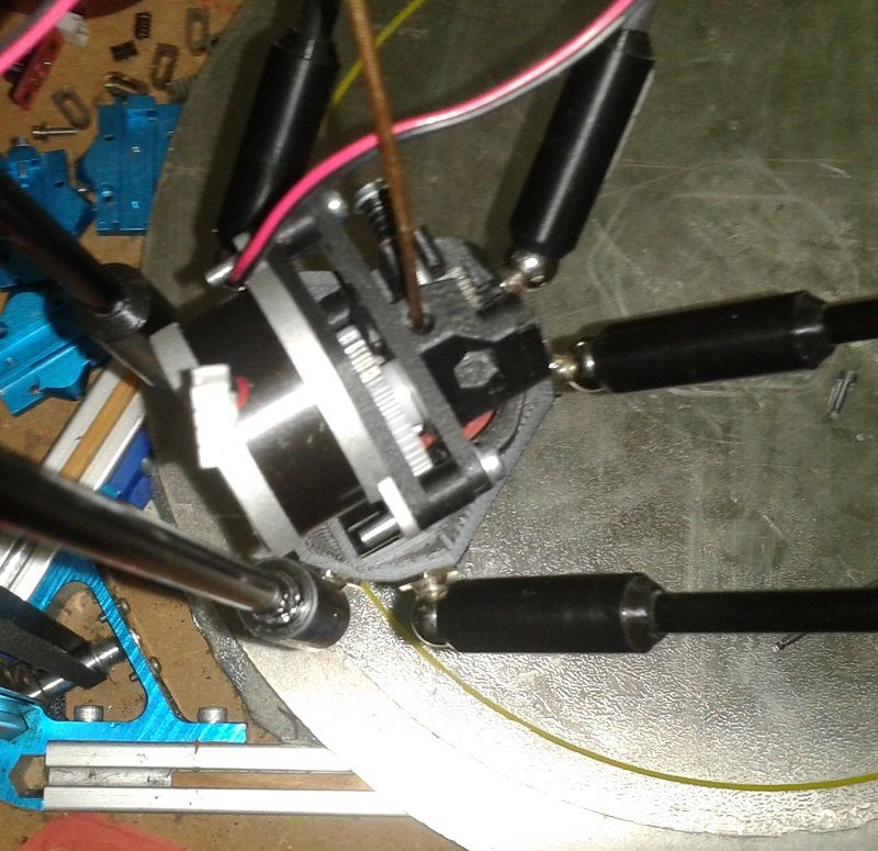
Can you spot the difference?

@garyd9
horrified by a TES value of ~8, I decided to install the 55mm smart effector carrier PCBs again. To my surprise the extruder fits very well, the max. printable radius is only slightly smaller than before.
That was achieved by an 8mm center => nozzle offset. The COG is better than the other approaches, who simply increased the rod spacing. And from the looks, I think, I can use 12mm 'b' distance, without any disadvantage. Then I'd have the same TES than the SmartEffector.@dc42 if you read this, would it be possible to use the strain gauge technology when the nozzle is 8mm offcenter?
-
@o_lampe said in [Delta] Rod spacing 20mm, Pros & Cons?:
That was achieved by an 8mm center => nozzle offset. The COG is better than the other approaches, who simply increased the rod spacing. And from the looks, I think, I can use 12mm 'b' distance, without any disadvantage. Then I'd have the same TES than the SmartEffector.
This is interesting, and while it works for the sherpa-based extruder, I don't think it would work for the currently released Orbiter extruders. For that, I think you'd have to increase the offset by another 8-10mm -- and/or some kind of adapter that raises and tilts the extruder.
One thing is for sure, however: regardless of what it takes to accomplish, the 3D printing community WILL figure it out.
-
@garyd9
There's one more difference in my setup regarding to Smart Effector: The ballstuds are horizontal, while they are vertical on the SE. That adds another few mm to raise. But less then others needed with the nozzle being at center.
I just had a weird idea: if we'd raise the extruder gear high enough, we could probably put the motor below the spur gear
//edit from eyeballing that wouldn't fit easily...
