Extruder motor doesn't move
-
@phaedrux ; Configuration file for Duet WiFi (firmware version 3)
; executed by the firmware on start-up
;
; generated by RepRapFirmware Configuration Tool v3.2.3 on Thu Jun 10 2021 17:46:43 GMT-0400 (Eastern Daylight Time); General preferences
G90 ; send absolute coordinates...
M83 ; ...but relative extruder moves
M550 P"My Printer" ; set printer name; Network
M552 S1 ; enable network
M586 P0 S1 ; enable HTTP
M586 P1 S0 ; disable FTP
M586 P2 S0 ; disable Telnet; Drives
M569 P0 S0 ; physical drive 0 goes backwards
M569 P1 S0 ; physical drive 1 goes backwards
M569 P2 S0 ; physical drive 2 goes backwards
M569 P3 S1 ; physical drive 3 goes forwards
M584 X0 Y1 Z2 E3 ; set drive mapping
M350 X16 Y16 Z16 E16 I1 ; configure microstepping with interpolation
M92 X80.00 Y80.00 Z400.00 E420.00 ; set steps per mm
M566 X900.00 Y900.00 Z60.00 E120.00 ; set maximum instantaneous speed changes (mm/min)
M203 X6000.00 Y6000.00 Z180.00 E1200.00 ; set maximum speeds (mm/min)
M201 X500.00 Y500.00 Z20.00 E250.00 ; set accelerations (mm/s^2)
M906 X800 Y800 Z800 E800 I30 ; set motor currents (mA) and motor idle factor in per cent
M84 S30 ; Set idle timeout; Axis Limits
M208 X0 Y0 Z0 S1 ; set axis minima
M208 X230 Y210 Z200 S0 ; set axis maxima; Endstops
M574 X1 S1 P"!xstop" ; configure active-high endstop for low end on X via pin !xstop
M574 Y1 S1 P"!ystop" ; configure active-high endstop for low end on Y via pin !ystop
M574 Z1 S1 P"!zstop" ; configure active-high endstop for low end on Z via pin !zstop; Z-Probe
M558 P0 H5 F120 T6000 ; disable Z probe but set dive height, probe speed and travel speed
M557 X15:215 Y15:195 S20 ; define mesh grid; Heaters
M308 S0 P"bedtemp" Y"thermistor" T100000 B4138 ; configure sensor 0 as thermistor on pin bedtemp
M950 H0 C"bedheat" T0 ; create bed heater output on bedheat and map it to sensor 0
M307 H0 B1 S1.00 ; enable bang-bang mode for the bed heater and set PWM limit
M140 H0 ; map heated bed to heater 0
M143 H0 S120 ; set temperature limit for heater 0 to 120C
M308 S1 P"e0temp" Y"thermistor" T100000 B4138 ; configure sensor 1 as thermistor on pin e0temp
M950 H1 C"e0heat" T1 ; create nozzle heater output on e0heat and map it to sensor 1
M307 H1 B0 S1.00 ; disable bang-bang mode for heater and set PWM limit
M143 H1 S280 ; set temperature limit for heater 1 to 280C; Fans
M950 F0 C"fan0" Q500 ; create fan 0 on pin fan0 and set its frequency
M106 P0 S0 H-1 ; set fan 0 value. Thermostatic control is turned off
M950 F1 C"fan1" Q500 ; create fan 1 on pin fan1 and set its frequency
M106 P1 S1 H1 T45 ; set fan 1 value. Thermostatic control is turned on; Tools
M563 P0 D0 H1 F0 ; define tool 0
G10 P0 X0 Y0 Z0 ; set tool 0 axis offsets
G10 P0 R0 S0 ; set initial tool 0 active and standby temperatures to 0C; Custom settings are not defined
-
@phaedrux Another question I have is: what is the unit of the numbers in the machine movement control? Is it mm?

-
Yes that is movement in millimeters.
-
Add this
T0
M302 P1 ; Allow cold extrusionto the end of your config.g and see if you're able to activate the extruder then.
If that doesn't work, Since this is a tool that will be using an external heater controller you could follow the advice in the cold extrusion wiki entry to define the tool without a heater associated at all.
https://duet3d.dozuki.com/Wiki/Gcode#Section_M302_Allow_cold_extrudes
Note: One limitation of M302 is that it requires a thermistor to be present for the temperature to be monitored. If your system does not have a thermistor or heater to be monitored, you can define your tool in M563 without a heater to disable cold extrusion protection on that tool. ex: M563 P0 S"Pump" D0 F0 Note the lack of H parameter.
So in your case
; Tools
M563 P0 D0 H1 F0 ; define tool 0
You would remove the H1 entirely.
-
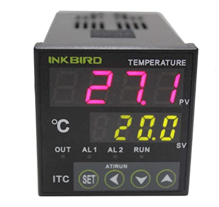
@phaedrux I want to send the temperature signal from PID to the Duet board, do I need adapters to do it? I saw online there's some kind of daughter board for thermocouple. I'm using Duet 2 ethernet, which daughter board should I purchase?
-
Can you give more info on your external temperature controller?
-
@phaedrux It's a very common Inkbird PID controller. The thermocouple from the extruder head is a K-type thermocouple.

-
If the thermocouple is already going to the PID controller how do you hope to connect it to the Duet as well?
Do you have a link for that unit?
-
@phaedrux I plan to use a dual thermocouple connector to split the thermocouple signal, so that one goes to the PID and the other goes to the Duet board.
-
Ok, yes if you've got a dual thermocouple with two junctions with their own wires then yes, you could run one to the controller and one to the Duet. You would need the Duet Thermocouple Daughterboard to be able to read the temp.
https://duet3d.dozuki.com/Wiki/Thermocouple_daughter_board
https://duet3d.dozuki.com/Wiki/Connecting_thermocouples -
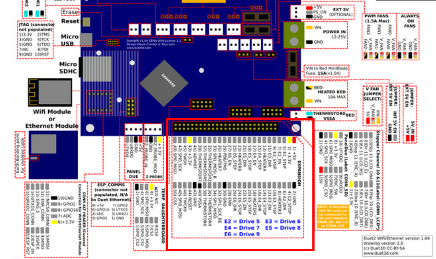
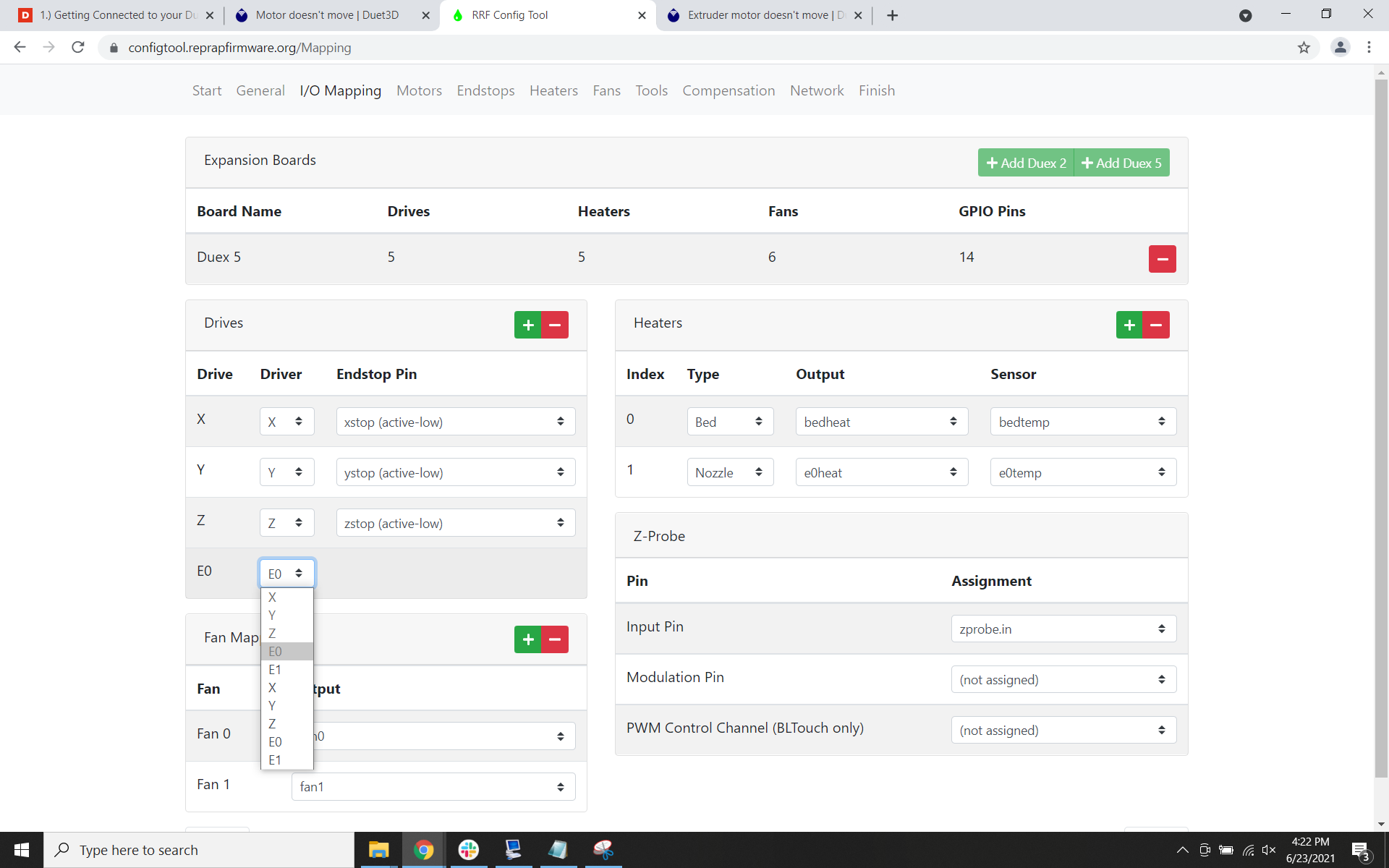
Hi, now the temperature is all set, but I have some problems with the extruder motor. I used the expansion portion (highlighted in the red square shown below) of the board for extruder signals. The channels I connected are E2, but I couldn't setup the config file to use the E2 motor because it isn't listed.


-
You'll need to alter the config manually to add non-standard mappings.
-
@phaedrux Could you please explain how to do that?
-
If you're using E2 that equates to driver 5 on the duex.
So in your M584 command, For the extruder drives you would list all the extruder that will be connected to the main Duet drivers and then add 5 for the expansion header.
M584 X0 Y1 Z2:3 E4:5just as an example.Have you seen this yet? https://duet3d.dozuki.com/Wiki/Using_external_stepper_motor_drivers
-
@phaedrux Hi, my extruder motor needs 5V, while the Duet board output is 3.3V, I'm thinking of buying a breakout board like this:
https://duet3d.dozuki.com/Wiki/Duet_Expansion_Breakout_Board
Will it work? -
@zfeng said in Extruder motor doesn't move:
my extruder motor needs 5V,
I'm not sure what you mean by this. The stepper motor drivers are constant current drivers. The rated voltage on the motor isn't a requirement.
-
@phaedrux I'm not using motor drive output, I'm using the expansion portion of the board, which is 3.3V output. But my extruder motor needs 5V.

-
@phaedrux Since I'll use the E2 of the expansion to wire my extruder motor, how to modify the config code to use the E2? I won't use the E0 and E1.
My config.g Driver code is below:
; Drives
M569 P0 S0 ; physical drive 0 goes backwards
M569 P1 S0 ; physical drive 1 goes backwards
M569 P2 S1 ; physical drive 2 goes forwards
M584 X0 Y1 Z2 ; set drive mapping
M350 X16 Y16 Z16 I1 ; configure microstepping with interpolation
M92 X80.00 Y80.00 Z400.00 ; set steps per mm
M566 X900.00 Y900.00 Z60.00 ; set maximum instantaneous speed changes (mm/min)
M203 X6000.00 Y6000.00 Z180.00 ; set maximum speeds (mm/min)
M201 X500.00 Y500.00 Z20.00 ; set accelerations (mm/s^2)
M906 X800 Y800 Z800 I30 ; set motor currents (mA) and motor idle factor in per cent
M84 S30 ; Set idle timeout -
@zfeng said in Extruder motor doesn't move:
Since I'll use the E2 of the expansion to wire my extruder motor, how to modify the config code to use the E2?
I already answered that I think.
@phaedrux said in Extruder motor doesn't move:
If you're using E2 that equates to driver 5 on the duex.
So in your M584 command, For the extruder drives you would list all the extruder that will be connected to the main Duet drivers and then add 5 for the expansion header.
M584 X0 Y1 Z2:3 E4:5just as an example.Have you seen this yet? https://duet3d.dozuki.com/Wiki/Using_external_stepper_motor_drivers
@zfeng said in Extruder motor doesn't move:
I'm not using motor drive output, I'm using the expansion portion of the board, which is 3.3V output. But my extruder motor needs 5V.
Do you mean your external driver needs 5v?
-
@phaedrux Yes my external driver needs 5V, will this breakout board work for my case?
https://duet3d.dozuki.com/Wiki/Duet_Expansion_Breakout_Board