Setting up Accelerometer and wiring
-
@dc42 said in Setting up Accelerometer and wiring:
yes that is the typical error. The CS pin must come first.
exp.pa21 = EXP_0
exp.pa22 = EXP_1Right?
-
@reczul-01 You must be on v3.4-b1 from the unstable package feed in order to use accelerometers in SBC mode. Your error message indicates that you are still running RRF 3.3 which does not support file operations on the SBC.
@CCS86 Yes, that's right.
-
@bot said in Setting up Accelerometer and wiring:
@dc42 I've had a theory for a while that the thin heatbreak of the common E3D V6 moves a lot during printing. Perhaps it would be beneficial to mount the accelerometer directly to the (cold) heat block?
See this rudimentary analysis of resonant frequencies I did:
Probably it would be useful to design a bracket that mounts the sensorboard on the (cold) heaterblock? It's meant to be a temporary installation anyway until you've dialed in the input shaper.
-
@ccs86 said in Setting up Accelerometer and wiring:
@dc42 said in Setting up Accelerometer and wiring:
yes that is the typical error. The CS pin must come first.
exp.pa21 = EXP_0
exp.pa22 = EXP_1Right?
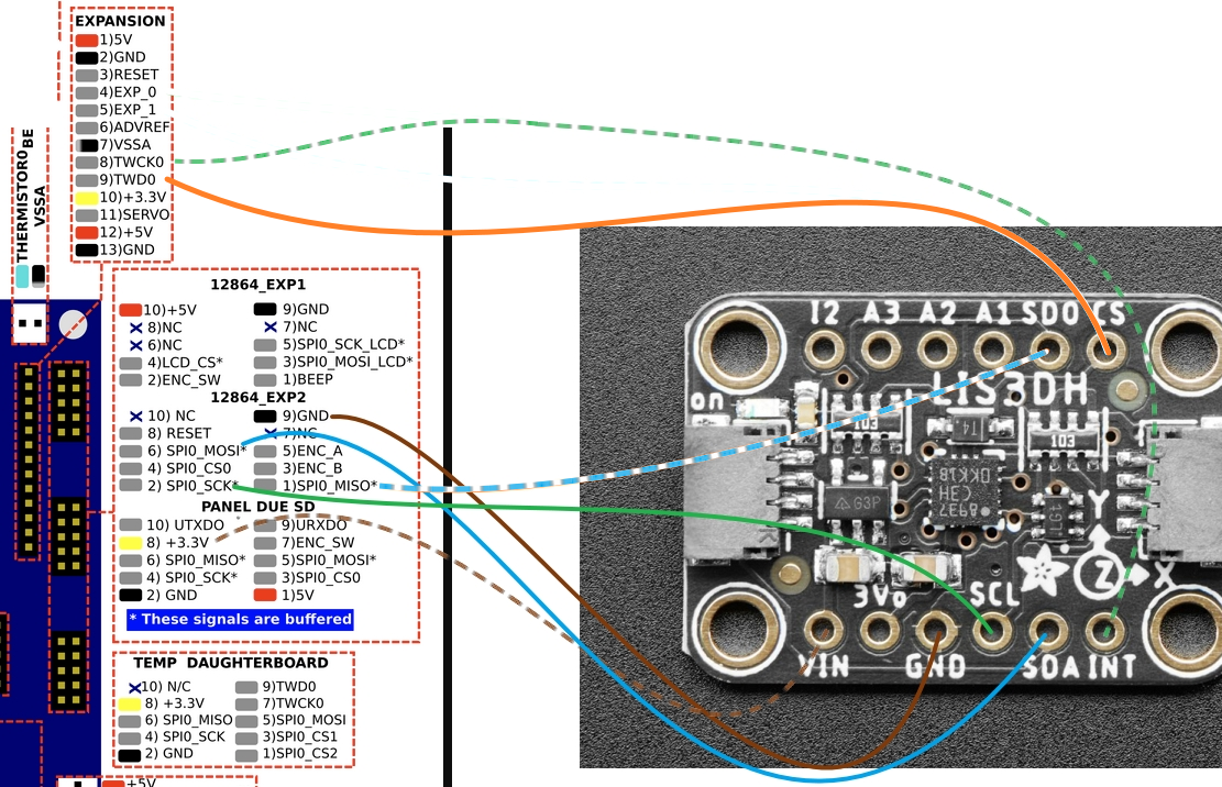
You can also try using the TWC0 and TWD0 pins instead of EXP0 and EXP1.
Duet WiFi hardware designer and firmware engineer
Please do not ask me for Duet support via PM or email, use the forum
http://www.escher3d.com, https://miscsolutions.wordpress.com -
When using twisted pair cable, which wires would be most important to keep further apart?
-
@o_lampe I suppose it wouldn't hurt to do that. However, as dc42 pointed out, and I seem to have confirmed by doing a few more very rudimentary FEA tests, the frequency that is excited with the geometry of the hot end is quite high.
I think other users have done tests and experiments that show that these ringing frequencies originate in the belts and motors. The frame and other components are not likely vibrating excessively at the low frequencies that we see in ringing.
-
@bot
I didn't mean that the heatsink/hotend add to the equation, but the long lever of the heatsink amplifies the amplitude which makes it easier to separate resonance from noise.
And it would be easier to design a universal bracket, since most heatblocks share more or less the same dimensions. While brackets for carriers are often one_of_a_kind. -
@dc42 said in Setting up Accelerometer and wiring:
You can also try using the TWC0 and TWD0 pins instead of EXP0 and EXP1.
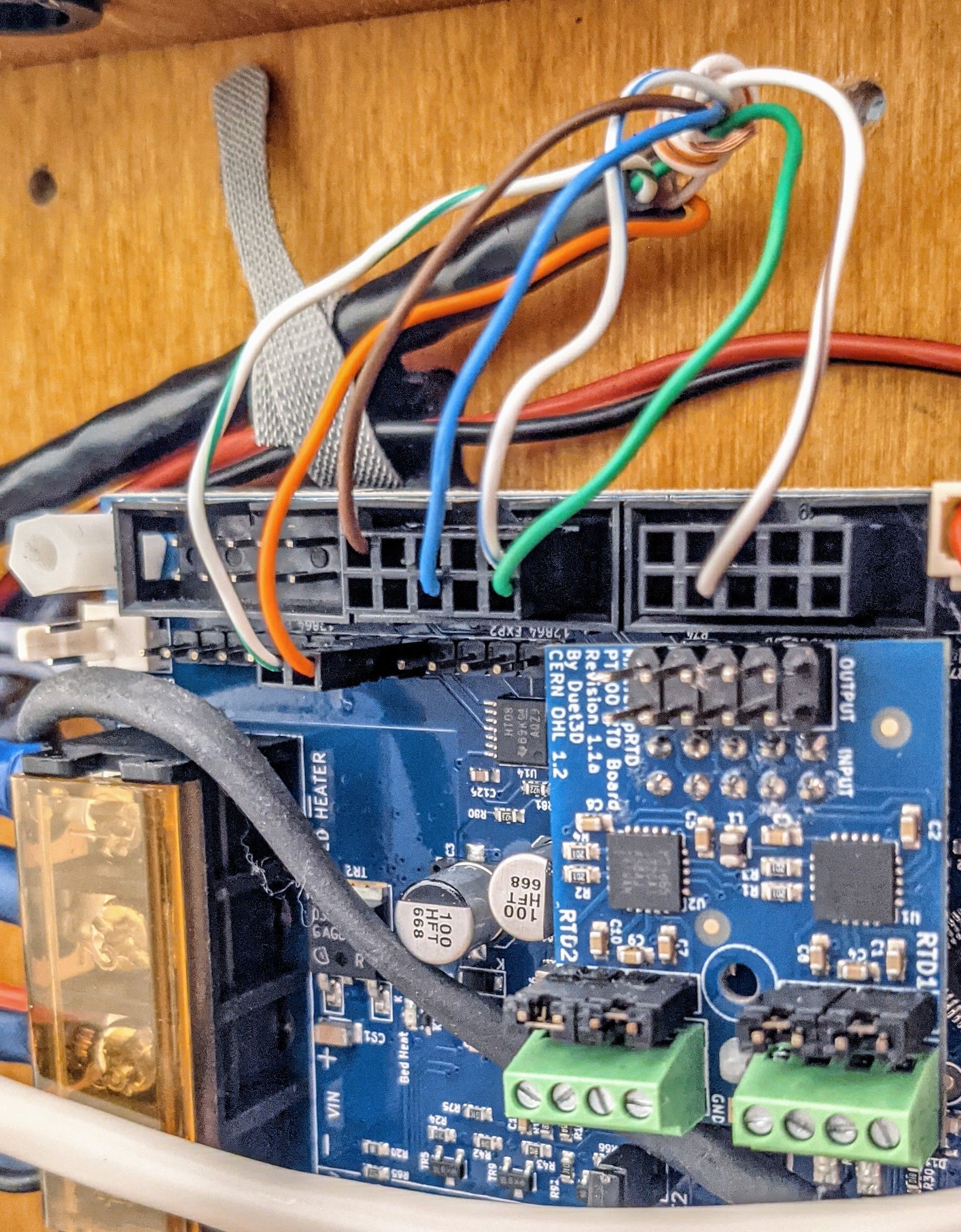
I re-wired the whole thing with the shortest CAT6 cable I can manage. I kept the 1k resistor inline with SDO... same error.
I moved CS and INT as follows:
CS > TWD0
INT > TWCK0M955 P0 C"exp.pa3+exp.pa4"
...same error. Accelerometer not found. Green light is lit on the accelerometer.
What else can I do to troubleshoot?
-
-
-
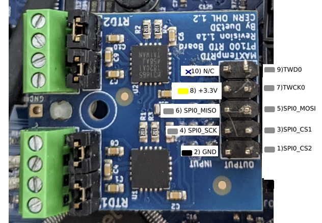
@ccs86 have you already tried the SPI Pins on the Temp Board? The SPI Pins on the EXP are bufferd
-
@pcr said in Setting up Accelerometer and wiring:
@ccs86 have you already tried the SPI Pins on the Temp Board? The SPI Pins on the EXP are bufferd
I can try that. Can't seem to find the correct pin names for those, though. I have tried:
M955 P0 C"spi.PB2+spi.PC18"
M955 P0 C"PB2+PC18"
M955 P0 C"spi0_cs1+spi0_cs2"
M955 P0 C"spi0.cs1+spi0.cs2"
M955 P0 C"spi.cs1+spi.cs2"
M955 P0 C"spi.cs3+spi.cs4"
M955 P0 C"exp.cs1+exp.cs2"
M955 P0 C"exp.cs3+exp.cs4"This page seems incomplete for pin names: https://duet3d.dozuki.com/Wiki/Duet_2_Maestro_Wiring_Diagram
And I'm not sure this is applicable: https://duet3d.dozuki.com/Wiki/Duet_2_Pinout_table
-
@ccs86 yes that page is missing the SPI CS pin names. They are "spi.cs1" and "spi.cs2".
Duet WiFi hardware designer and firmware engineer
Please do not ask me for Duet support via PM or email, use the forum
http://www.escher3d.com, https://miscsolutions.wordpress.com -
@dc42 said in Setting up Accelerometer and wiring:
@ccs86 yes that page is missing the SPI CS pin names. They are "spi.cs1" and "spi.cs2".
Are these pins used by the daughterboard itself? I get the following error:
M955 P0 C"spi.cs1+spi.cs2"
Error: M955: Pin 'spi.cs1' is not free
Any other ideas?
-
@ccs86 yes you are already using those pins for the daughter board.
Duet WiFi hardware designer and firmware engineer
Please do not ask me for Duet support via PM or email, use the forum
http://www.escher3d.com, https://miscsolutions.wordpress.com -
@dc42 said in Setting up Accelerometer and wiring:
@ccs86 yes you are already using those pins for the daughter board.
Any ideas on what to try next?
-
@ccs86 I'll try hooking up an accelerometer to a Maestro when I get a chance.