Is this a type for X and Y?
-
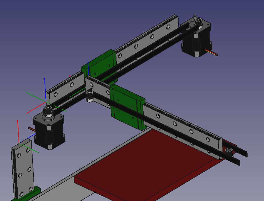
Was wondering is this would work for x and y axis?
Single looped belt attached to front Y block, with 2 motors. Y rail is attached to X block.
Please note this is a before draft, just to see if this config would work and if so what is its name for custom firmware. a lot of parts missing.
Thanks!
`mike
-
@gallaghersart I don't understand what I am looking at.
Maybe you could do some paper and pencil drawings and scan those in showing where the belt goes and where it's attached.
-
It's hard to see from the drawing where you are going with this approach.
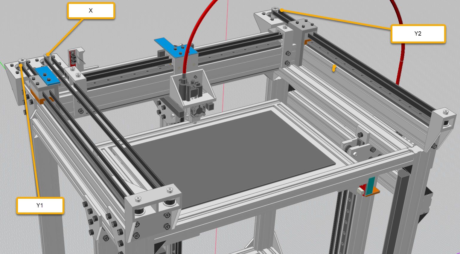
There is this type using two steppers for Y and one for X. Is the something like what you are thinking of?
Printers: a E3D MS/TC setup and a RatRig Hybrid. Using Duet 3 hardware running 3.4.6
-
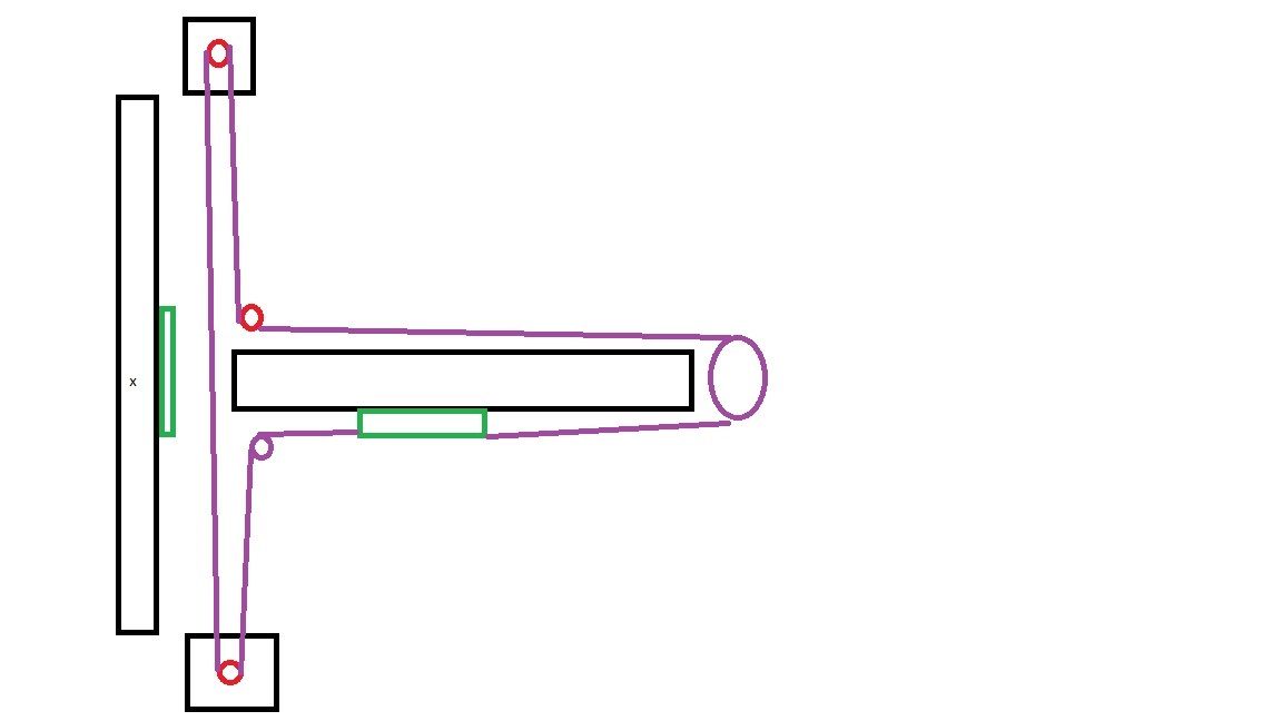
real crap drawing from paint nothing lined up, but see belt path only connected to motors and y plate for the belts ends, half core XY?
-
@gallaghersart OK, I see.
Those two motors working together will move the green part left and right in your diagram.
That will work well.
I guess there is another motor that will move the carriage along the X-axis rail?
When that motor moves, the two other motors are going to also have to move if you want the carriage to stay in the same location left-to-right. -
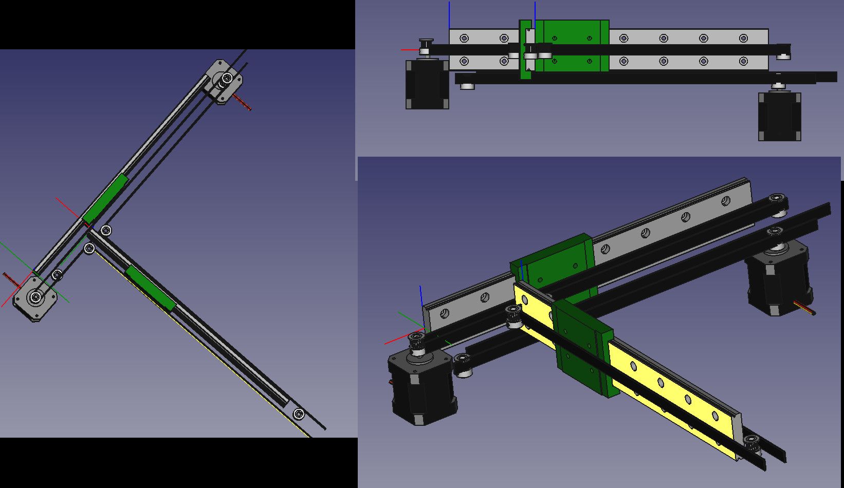
@fcwilt I think your config is like what I’m talking about but with only 1 y motor as arm will hang off X. I added a second belt ,one for x and one for y like I think you have.
-
What is gained by having two stepper motors doing the same thing? Is the torque requirement too much for one stepper? If so, why not use just one 23 size and free up a redundant stepper driver port?
-
@kb58 1st image I had wrong 2 motors 2 belts. 1st image would gain nothing
-
@gallaghersart said in Is this a type for X and Y?:
@fcwilt I think your config is like what I’m talking about but with only 1 y motor as arm will hang off X. I added a second belt ,one for x and one for y like I think you have.
What do you mean by "hang off X"?
Thanks.
Frederick
-
@gallaghersart It looks like you're trying to make something like an H-bot mechanism with a cantilevered end instead of having a second Y axis rail. While it may be able to position the carriage in X and Y, getting it to produce quality 3D prints is another problem.
The carriage guide rail (let's call it X for brevity) is cantilevered out into space. When the whole X axis is sliding along the Y axis and comes to an abrupt stop, what stops the end of the X axis from wobbling back and forth? What happens when the carriage with extruder or spindle is at the free end of the X axis when the Y axis comes to an abrupt stop?
It's a big variable frequency, horizontal pendulum. Getting it to behave well enough to print (or mill) would require really massive mechanical assembly, especially where the two guide rails meet.
In the vertical direction, what happens to the free end of the X axis as the carriage moves along the X axis? When the carriage is near the free end, the X axis will bend down. When the carriage is near the Y axis the end of the X axis will go back to almost horizontal. So the mill bit or extruder nozzle will go up and down as the carriage moves along the X axis, all the while wobbling horizontally. Ugh!
Cantilevers are difficult to make work if you're trying to do any high accuracy/precision work.
But maybe you're not intending to use it to print or mill...
-
@mrehorstdmd said in Is this a type for X and Y?:
Getting it to behave well enough to print (or mill) would require really massive mechanical assembly, especially where the two guide rails meet.
...
Cantilevers are difficult to make work if you're trying to do any high accuracy/precision work.I agree cantilevers on their own are impractical, but I had good results with the dual roller constraint to support the open side of a cantilevered bed or such. No sagging or racking, even without 'massive mechanical assembly'.
@gallaghersart check out my YT channel to see some examples (eg. cloverleaf drive , penplotter and dual roller contraint demo)