Large Format Dowell to Duet conversion
-
It says:
29/10/2021, 12:04:40 M120 G91 G1 Z50 F6000 G90 M121 Error: G0/G1: insufficient axes homed -
I sent it
G92 X600 Y600 Z200And when I try to move the z -100 it makes a noise like a fan is going off and motors are locking but no movement
-
@charles-fraser ok try much sorter moves like 0.1 and see if that works. you can observe if the Z motors are rotating smoothly. Also is the bed trammed level so the leadscrews are not binding?
-
bed is super level, no movement just noises
-
Could it be I should send higher mA to the drives?
; Drives M569 P0.0 S1 ; physical drive 0.0 goes forwards M569 P0.1 S1 ; physical drive 0.1 goes forwards M569 P0.2 S1 ; physical drive 0.2 goes forwards M569 P0.3 S1 ; physical drive 0.3 goes forwards M569 P0.4 S1 ; physical drive 0.4 goes forwards M569 P0.5 S1 ; physical drive 0.5 goes forwards M569 P1.0 S1 ; physical drive 1.0 goes forwards M584 X0.0 Y0.1 Z0.2:0.4:0.5:0.3 E1.0 M350 X16 Y128 Z16 E16 I1 ; configure microstepping with interpolation M92 X80.00 Y1280.00 Z400.00 E420.00 ; set steps per mm M566 X900.00 Y900.00 Z60.00 E120.00 ; set maximum instantaneous speed changes (mm/min) M203 X6000.00 Y6000.00 Z180.00 E1200.00 ; set maximum speeds (mm/min) M201 X500.00 Y500.00 Z20.00 E250.00 ; set accelerations (mm/s^2) M906 X2800 Y2800 Z1200 E1200 I30 ; set motor currents (mA) and motor idle factor in per cent M84 S30 ; Set idle timeout -
@charles-fraser it could be, where did those values come from originally? What Z motors do you have? also are you sure your Z steps/mm are right?
-
I just took standard NEMA17 1.6A power rating
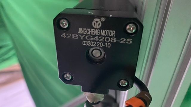
The actual motor spec I can't find anywhere:


It's a screw with a lead of 5mm. It's defo not moving if I put +100 or +0.1 so is it really an issue with steps per mm ?
-
@charles-fraser said in Large Format Dowell to Duet conversion:
is it really an issue with steps per
assuming the gearing of those pulleys is 1.8:1 then 400 is correct I think. Other wise is probably not so far of that nothing moves when you only move 0.1mm in ZWithe the power turned off can you disconnect a Z motor and check the continuity of the two coils with a multi meter. Of the the 4 pins on the plug that you are plugging into the duet there should be two pairs of wires with low resistance.
-
Hi Tody I checked the pairs when wiring but I will double check now
-
@charles-fraser if the two pairs are pins 1-2 and pins 3-4 for the Z motors then the next step is to see if the motors turn individually, without the belts connected.
-
yup the pairs are pins 1+2 and 3+4
so I loosened the belt and stuck a sticker atop the motor so I can see it spinning and it does spin now the tension is off the belt.
-
@t3p3tony it just sounds like the one z motor is trying to move though
-
-
Okay +50 takes it +10 closer to the nozzle, i.e the bed goes up. I'm pretty sure we want + to make the bed go father from the nozzle right? Anyway, I will times the steps per mm by 5
-
-
@charles-fraser said in Large Format Dowell to Duet conversion:
I'm pretty sure we want + to make the bed go father from the nozzle right?
yes Z+ should increase the gap between the nozzle and the Bed. this is controlled with the S parameter in M569:
M569 P0.2 S1                                                    ; physical drive 0.2 goes forwards
M569 P0.3 S1                                                    ; physical drive 0.3 goes forwards
M569 P0.4 S1                                                    ; physical drive 0.4 goes forwards
M569 P0.5 S1                                                    ; physical drive 0.5 goes forwards
assumming all the Z motors are turning the same way then this should reverse that direction.
M569 P0.2 S0 ; physical drive 0.2 goes forwards M569 P0.3 S0 ; physical drive 0.3 goes forwards M569 P0.4 S0 ; physical drive 0.4 goes forwards M569 P0.5 S0 ; physical drive 0.5 goes forwards -
@Charles-Fraser please do me a favour, after you have made those changes and tested them post your full config.g here again - Is getting harder to quickly find it higher up the thread.
-
They are all moving up and down in the same direction yes
Configuration file for Duet 3 (firmware version 3.3) ; executed by the firmware on start-up ; ; generated by RepRapFirmware Configuration Tool v3.3.3 on Fri Oct 01 2021 16:59:54 GMT+0100 (British Summer Time) ; General preferences G90 ; send absolute coordinates... M83 ; ...but relative extruder moves ; Wait a moment for the CAN expansion boards to start G4 S2 ; Drives M569 P0.0 S1 ; physical drive 0.0 goes forwards M569 P0.1 S1 ; physical drive 0.1 goes forwards M569 P0.2 S0 ; physical drive 0.2 goes forwards M569 P0.3 S0 ; physical drive 0.3 goes forwards M569 P0.4 S0 ; physical drive 0.4 goes forwards M569 P0.5 S0 ; physical drive 0.5 goes forwards M569 P1.0 S1 ; physical drive 1.0 goes forwards M584 X0.0 Y0.1 Z0.2:0.4:0.5:0.3 E1.0 M350 X16 Y128 Z16 E16 I1 ; configure microstepping with interpolation M92 X80.00 Y1280.00 Z2000.00 E420.00 ; set steps per mm M566 X900.00 Y900.00 Z60.00 E120.00 ; set maximum instantaneous speed changes (mm/min) M203 X6000.00 Y6000.00 Z180.00 E1200.00 ; set maximum speeds (mm/min) M201 X500.00 Y500.00 Z20.00 E250.00 ; set accelerations (mm/s^2) M906 X2800 Y2800 Z1200 E1200 I30 ; set motor currents (mA) and motor idle factor in per cent M84 S30 ; Set idle timeout ; Axis Limits M208 X0 Y0 Z0 S1 ; set axis minima M208 X1200 Y2000 Z1600 S0 ; set axis maxima ; Endstops M574 X1 S1 P"io1.in" ; configure active-high endstop for low end on X via pin io1.in M574 Y1 S1 P"io2.in" ; configure active-high endstop for low end on Y via pin io2.in M574 Z1 S1 P"io0.in" ; configure Z-probe endstop for low end on Z ; Z-Probe M558 P9 C"^1.io1.in" H100 F120 T6000 ; set Z probe type to switch and the dive height + speeds G31 P500 X0 Y0 Z2.5 ; set Z probe trigger value, offset and trigger height M556 S50 X0 Y0 Z0 ; set orthogonal axis compensation parameters M557 X15:215 Y15:195 S20 ; define mesh grid ; Heaters M308 S0 P"1.temp0" Y"PT1000" M950 H0 C"1.out0" T0 M307 H0 B1 R0.138 C790.6 D13.87 S1.00 V24.0 ; enable bang-bang mode for the bed heater and set PWM limit M140 H0 ; map heated bed to heater 0 M143 H0 S80 ; set temperature limit for heater 0 to 80C M308 S1 P"1.temp1" Y"PT1000" ; configure sensor 1 as thermistor on pin temp0 M950 H1 C"1.out1" T1 ; create nozzle heater output on out1 and map it to sensor 1 M307 H1 B0 S1.00 ; disable bang-bang mode for heater and set PWM limit M143 H1 S300 ; set temperature limit for heater 1 to 300C ; Fans M950 F0 C"out8" Q0 ; create fan 0 on pin out8 and set its frequency M106 P0 S0 H T45 ; set fan 0 value. Thermostatic control is turned on M950 F1 C"out9" Q500 ; create fan 1 on pin out9 and set its frequency M106 P1 S1 H-1 ; set fan 1 value. Thermostatic control is turned off ; Tools M563 P0 S"lily" D0 H1 F0:1 ; define tool 0 G10 P0 X100 Y100 Z0 ; set tool 0 axis offsets G10 P0 R0 S0 ; set initial tool 0 active and standby temperatures to 0C ; Custom settings are not defined -
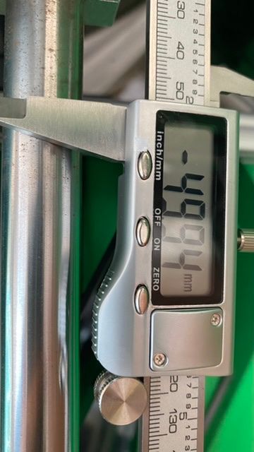
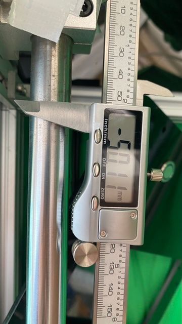
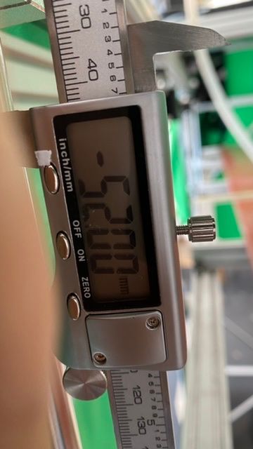
I am trying to work out how to calculate the steps per mm if 2000 s/mm is giving me 52mm translation when I send 50. I can't seem to work out how to work it out embarrassingly
-
M92 X80.00 Y1280.00 Z1926.78 E420.00 ; set steps per mmokay this seems to be near enough
If I divide 100,000 steps by 52mm I get
1926.78 s/mm ifWhen I use value z1926.00 I get the following on a 50mm command

If I divide 51.9 mm by 100,000 steps I get 1926.78
That translates to
They are both .1 of a mm out. Is that okay if I am printing big things. No not really it needs to be less.
So I go between those two z1926.39

