Duet2 Wifi and the Sidewinder X1 endstops
-
Hi Tony, I hope I posted it right.

undefined ```; generated by RepRapFirmware Configuration Tool v3.3.4 on Thu Oct 14 2021 13:13:53 GMT+0100 (British Summer Time) ; General preferences M575 P1 S1 B57600 ; enable support for PanelDue G90 ; send absolute coordinates... M83 ; ...but relative extruder moves M550 P"Artilley X1" ; set printer name ; Network M552 S1 ; enable network M586 P0 S1 ; enable HTTP M586 P1 S0 ; disable FTP M586 P2 S0 ; disable Telnet ; Drives M569 P0 S0 ; physical drive 0 goes forwards M569 P1 S1 ; physical drive 1 goes forwards M569 P2 S1 ; physical drive 2 goes forwards M569 P3 S1 ; physical drive 3 goes forwards M584 X0 Y1 Z2 E3 ; set drive mapping M350 X16 Y16 Z16 E16 I1 ; configure microstepping with interpolation M92 X80.00 Y80.00 Z400.00 E420.00 ; set steps per mm M566 X900.00 Y900.00 Z60.00 E120.00 ; set maximum instantaneous speed changes (mm/min) M203 X6000.00 Y6000.00 Z180.00 E1200.00 ; set maximum speeds (mm/min) M201 X500.00 Y500.00 Z20.00 E250.00 ; set accelerations (mm/s^2) M906 X800 Y800 Z800 E800 I30 ; set motor currents (mA) and motor idle factor in per cent M84 S30 ; Set idle timeout ; Axis Limits M208 X5 Y5 Z2.5 S1 ; set axis minima M208 X295 Y295 Z400 S0 ; set axis maxima ; Endstops M574 X1 S1 P"!^xstop" ; configure switch-type (e.g. microswitch) endstop for low end on X via pin !^xstop M574 Y2 S1 P"!^ystop" ; configure switch-type (e.g. microswitch) endstop for high end on Y via pin !^ystop M574 Z1 S1 P"!^zstop" ; configure switch-type (e.g. microswitch) endstop for low end on Z via pin !^zstop ; Z-Probe M558 P0 H5 F120 T6000 ; disable Z probe but set dive height, probe speed and travel speed M557 X20:280 Y20:280 S20 ; define mesh grid ; Heaters M308 S0 P"bedtemp" Y"thermistor" T100000 B4138 ; configure sensor 0 as thermistor on pin bedtemp M950 H0 C"bedheat" T0 ; create bed heater output on bedheat and map it to sensor 0 M307 H0 B1 S1.00 ; enable bang-bang mode for the bed heater and set PWM limit M140 H0 ; map heated bed to heater 0 M143 H0 S120 ; set temperature limit for heater 0 to 120C M308 S1 P"e0temp" Y"thermistor" T100000 B4138 ; configure sensor 1 as thermistor on pin e0temp M950 H1 C"e0heat" T1 ; create nozzle heater output on e0heat and map it to sensor 1 M307 H1 B0 S1.00 ; disable bang-bang mode for heater and set PWM limit M143 H1 S280 ; set temperature limit for heater 1 to 280C ; Fans M950 F0 C"fan0" Q500 ; create fan 0 on pin fan0 and set its frequency M106 P1 S1 H-1 ; set fan 0 value. Thermostatic control is turned off M950 F1 C"fan1" Q500 ; create fan 1 on pin fan1 and set its frequency M106 P1 S1 H1 T45 ; set fan 1 value. Thermostatic control is turned on ; Tools M563 P0 D0 H1 F0 ; define tool 0 G10 P0 X0 Y0 Z0 ; set tool 0 axis offsets G10 P0 R0 S0 ; set initial tool 0 active and standby temperatures to 0C -
@tisdai thanks. I am not familiar with those endstops so no idea if the !^ is required to invert the signal and enable the pullup resistor. Where did the requirement for those come from?
Try the following:
- Send M119 without the endstops triggered - confirm they are showing as "not stopped"
- Manually trigger the endstop or move the axis to a point where its triggered and then send M119 again - are they still showing as "not stopped"
- Change the config to removed the inversion and pullup M574 X1 S1 P"xstop" etc
- do tests 1 and 2 again to see if its any different.
-
Just tried all of them and x,y,z come up as "not Stopped" after moving all of the axis manually to try and trigger them they still come up as "not stopped" . Changed the config to M574 X1 S1 P"xstop" and the motors stay on but are not moving and you can not move them manually. Tried it multiple times with all different ways you suggested but nothing. if their is no other around it I will buy some other endstops that are compatible.
-
@tisdai step 3 should not cause the motors to come on, did you try to run home or move them in DWC? rather than that send M18 and then slowly move the manually to the stops and then send M119
-
@t3p3tony Sorry Tony misread it my fault when I sent the M18 then moved the x axis and then run M119 I get " X at min stop" and I used YAT terminal, is that right. That result was from the M574 X1 S1 P"xstop" that you asked me to do.
-
@tisdai ok so it sounds like removing the !^ form the endstop definitions for the type of endstop you have on the X axis works (I am not sure if the same type is fitted to all three axis so you need to test all 3)
-
@t3p3tony Sorry it took so long to reply to you Tony, yes that worked for manually moving all of the axis to the endstop but now none of them move at all when being homed in DWC
-
@tisdai if you manually move them to the center of the machine so nothing is being triggered. then send M119 what do you get?
then send G92 X150 Y150 and try and jog the axis +/- by 10mm. do they move, doe they move in the direction expected?
-
@t3p3tony said in Duet2 Wifi and the Sidewinder X1 endstops:
On the M119 I get the Error message Endstops - X: at min stop, Y: at max stop, Z: at min stop, Z probe: at min stop and when I use the G92 X150 Y150 I get I can get them to move 10mm on the x and y both ways ok but the z will only move on the + and all of them in the right direction.
-
@tisdai ok so the changes we made earlier did not fully sort the problem with the endstops (from you earlier report i thought it had).
So can you confirm if you get a change in the endstop status reported by M119 when the carriage is at the X and Y endstop (lets leave Z out of this for now). Please post both M119 outputs, and confirm what the X and Y M574 definitions are in config.g
-
@t3p3tony said in Duet2 Wifi and the Sidewinder X1 endstops:
M119 result is Endstops - X: at min stop, Y: at max stop, and result is M574 X1 S1 P"xstop" / M574 y1 S1 P"ystop" -
@tisdai and if you move them away from the stops?
-
I found a photo of an Artillery end stop switch that has a manufacturers part number visible, a GL-8H
According to the datasheet for those, they are intended for 12 to 24V operation, with NPN (switch to 0V) outputs.
The switches probably need the power connection (brown or orange) changing from the on board endstop connectors to an external supply.
Refs.
https://www.3djake.com/artillery/x-axis-limit-switch
https://www.aliexpress.com/item/4000139818315.html
https://www.makerstore.com.au/product/elec-gl8h/ -
@t3p3tony They just stay the same Endstops - X: at min stop, Y: at max stop,
Robert J If that is the case then I will either have to buy some new End Stop Limit Switches Suitable for the printer like these, https://www.amazon.co.uk/Printer-Limit-Switch-Suitable-Ender-3/dp/B09161Y56X/ref=pd_sbs_1/262-0198064-0338202?pd_rd_w=n7IMI&pf_rd_p=a3a7088f-4aec-4dbd-97cc-9a059581fe7b&pf_rd_r=SRH1F8T4A74C0AAGK3YG&pd_rd_r=4f8273e1-eae3-49ff-8b46-bf442db76b5e&pd_rd_wg=36QA2&pd_rd_i=B09161Y56X&psc=1
-
Thanks @rjenkinsgb for digging the model number out!
The endstops you linked would be easier wire for sure.
Alternatively you can connect the endstops you have in a similar manner to an NPN zprobe, but the endstop inputs of the duet are only 8V tolerant so you must use a diode for protection:
https://duet3d.dozuki.com/Wiki/Connecting_a_Z_probe#Section_NPN_output_normally_open_inductive_or_capacitive_sensorConnect the power wire of the endstops to VIN (12-24V) and then connect the input wire to the endstop via a diode, similar to this picture:
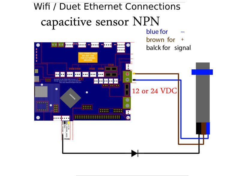
But to the endstop stp pin, not the zprobe input pin. Also note that you must use a diode, no matter what version of the duet, and it must be connected the correct way round.
-
@t3p3tony Thank you very much Tony I will buy the sensors I linked to will be easier all round, You have a great forum here with some very helpful members willing to take the time out to help others. Thanks to you too Richard for the info on the model number and info on the voltages helped me make my mind up a lot quicker.
-
@t3p3tony I bought those limit switches I linked to here
They are working ok I just had to alter the M574 code for the Endstops by adding ! to the X and Y Stop section and switch the wires around on the connectors to match the Duet2 wiring diagram.
M574 X1 S1 P"!xstop"
M574 Y2 S1 P"!ystop"
M574 Z1 S1 P"zstop"Thanks for your help appreciate it.