Duex 5 control relay
-
Hey guys,
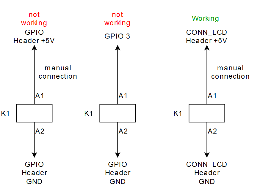
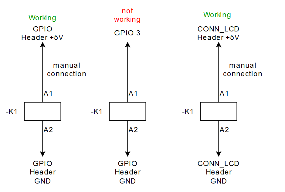
I would like to control a relay via the GPIOs of the Duex 5. If done that before on another printer. The problem is that its not working on the Duex 5. I got 5 V on the GPIO pin but the relay is not switching.
If I grab 5V from the duet2 the relay is working. If I grab 5V from the Duex5 it is not working.
I have nothing else on the 5V rail at the moment.Maybe relevant: I am using the 12V from the Duex5 to power an Arduino Nano but that should not make a difference.
According to the datasheet the Relay takes about 80mA.
https://de.farnell.com/schrack-te-connectivity/rt424005/relais-dpdt-250vac-8a/dp/1629052?ost=1629052
https://www.farnell.com/datasheets/1870236.pdfSo my question is:
Why?Custom ANET A8
Custom Delta: D-PATCH (Delta Printer with Automatic Tool CHanging) https://forum.duet3d.com/topic/16082/d-patch?_=1596131234754All I do here is under this license: CC BY-NC-SA
-
@taconite said in Duex 5 control relay:
If I grab 5V from the duet2 the relay is working.
Do you mean using +5V from the Duet 2 and switching the -'Ve side of the relay from the Duex5? The 5V on the Duex5 is supplied by the Duet2 so its the same supply.
Can you show a diagram of how you have it wired when its working, and when its not. also post how you are configuring it in both cases.
-
Hey Toni,
As per standard the positive side of the relay should to be switched.
part of config:

M950 P4 C"duex.gp3"																			;output relay
M42 P4 S1
and for completeness
; Configuration file for Duet WiFi (firmware version 3) ; executed by the firmware on start-up ; ; generated by RepRapFirmware Configuration Tool v2.1.8 on Fri Apr 10 2020 17:42:41 GMT+0200 (Mitteleuropäische Sommerzeit) ;--------------------------General preferences--------------------------------------------- ;------------------------------------------------------------------------------------------ G90 ; send absolute coordinates... M83 ; ...but relative extruder moves M550 P"D-Patch" ; set printer name ;M665 L403.609:403.609:403.609 R230.083 H410.261 B180.0 X0.003 Y-0.220 Z0.000 M665 L414:414:414 R210 H460 B150.0 X0 Y0 Z0.000 M666 X0 Y00 Z0 A0.00 B0.00 M665 L414.000:414.000:414.000 R239.006 H464.897 B150.0 X0.439 Y0.151 Z0.000 M666 X0.151 Y-0.537 Z0.386 A0.00 B0.00 M665 L414.000:414.000:414.000 R232.821 H464.366 B150.0 X-0.683 Y-0.638 Z0.000 M666 X-0.277 Y-0.601 Z0.878 A0.00 B0.00 ;---------------------------Network------------------------------------------------------- ;------------------------------------------------------------------------------------------ M552 S1 ; enable network M586 P0 S1 ; enable HTTP M586 P1 S0 ; disable FTP M586 P2 S0 ; disable Telnet ;---------------------------Motor remapping for toolchanger-------------------------------- ;------------------------------------------------------------------------------------------ ;M584 X0 Y1 Z2 U3 V4 E5:6:7:8:9 ; Driver X=0, Y=1, Z=2, U=3, v= 4, Extruder 5 and 6 7 8 9, remapping the drives M584 X0 Y1 Z2 E5:6:7:8:9 ;for testing without toolchanger ;----------------------------Drives-------------------------------------------------------- ;------------------------------------------------------------------------------------------ ;----------------------------forward/backward---- M569 P0 S1 ;x physical drive 0 goes forwards M569 P1 S1 ;y physical drive 1 goes forwards M569 P2 S1 ;z physical drive 2 goes forwards M569 P3 S0 ;u physical drive 3 goes backwards M569 P4 S1 ;v physical drive 4 goes backwards M569 P5 S0 ;e0 physical drive 5 goes forwards M569 P6 S0 ;e1 physical drive 6 goes forwards M569 P7 S0 ;e2 physical drive 7 goes forwards M569 P8 S1 ;e3 physical drive 8 goes forwards M569 P9 S1 ;e4 physical drive 9 goes backwards ;--------------------------Microstepping--------- M350 X16 Y16 Z16 U16 V16 I1 ; configure microstepping with interpolation M350 E16:16:16:16:16 I1 ; configure microstepping with interpolation ;--------------------------Steps per mm---------- M92 X160.00 Y160.00 Z160.00 U3200.00 V150.00 ; set steps per mm M92 E410.00 E410.00 E410.00 E410.00 E410.00 ; set steps per mm ;--------------------------Jerk------------------ M566 X400.00 Y400.00 Z400.00 U5 V0 ; set maximum instantaneous speed changes (mm/min) (U and V former 600 now 50 and 300) xyzE former 1200 now 50 M566 E150.00:150.00:150.00:150.00:150.00 ;--------------------------v max----------------- M203 X18000 Y18000 Z18000 U500 V2000 ; set maximum speeds (mm/min) (u former 700)1500 M203 E6000:6000:6000:6000:6000 ; set maximum speeds (mm/min) ;--------------------------a--------------------- M201 X10000.00 Y10000.00 Z10000.00 U50 V25 ;10.10.2020;3000 set accelerations (mm/s^2) (former 1000 and 1000 now 50 and 500) 200 M201 E5000.00:5000.00:5000.00:5000.00:5000.00 ;--------------------------Motor currents-------- M906 X1300 Y1300 Z1300 U1000 V2200 I30 ; set motor currents (mA) and motor idle factor in per cent M906 E1000:1000:1000:1000:1000 I30 ; set motor currents (mA) and motor idle factor in per cent M84 S30 ; Set idle timeout ;------------------------------------Axis Limits------------------------------------------- ;------------------------------------------------------------------------------------------ M208 Z-3 S1 ; set minimum Z ;------------------------------------Endstops---------------------------------------------- ;------------------------------------------------------------------------------------------ M574 X2 S1 P"!xstop" ; configure active-high endstop for high end on X via pin xstop M574 Y2 S1 P"!ystop" ; configure active-high endstop for high end on Y via pin ystop M574 Z2 S1 P"!zstop" ; configure active-high endstop for high end on Z via pin zstop M574 U1 S1 P"e0stop" ; configure active-high endstop for low end on U via pin e0stop M574 V1 S1 P"e1stop" ; configure active-high endstop for low end on V via pin e1stop ;------------------------------------Filament runout---------------------------------------------- ;------------------------------------------------------------------------------------------ M591 D5 P1 C"duex.e2stop" S1 ; D extruder drive, P type of sensor (1=Simple Sensor), C pin name, S1 enabled M591 D6 P1 C"duex.e3stop" S1 ; D extruder drive, P type of sensor (1=Simple Sensor), C pin name, S1 enabled M591 D7 P1 C"duex.e4stop" S1 ; D extruder drive, P type of sensor (1=Simple Sensor), C pin name, S1 enabled M591 D8 P1 C"duex.e5stop" S1 ; D extruder drive, P type of sensor (1=Simple Sensor), C pin name, S1 enabled M591 D9 P1 C"duex.e6stop" S1 ; D extruder drive, P type of sensor (1=Simple Sensor), C pin name, S1 enabled ;------------------------------------Z-Probe----------------------------------------------- ;------------------------------------------------------------------------------------------ M558 P5 C"^!zprobe.in+zprobe.mod" H5 F120 T6000 ; set Z probe type to switch (NC), Invert (!) (so NO), enable Pullup (^) and the dive height (5mm) + speeds (120 mm/min) M558 H30 ;*** Remove this line after delta calibration has been done and new delta parameters have been saved G31 P500 X0 Y0 Z1.6 ; set Z probe trigger value, offset and trigger height M557 R120 S15 ; define mesh grid; Radius 120, Distance 10mm ;-----------------------------------Heaters------------------------------------------------ ;------------------------------------------------------------------------------------------ ;-------------Creation of Sensor 0 (Bed)----------------- M308 S0 P"bedtemp" Y"thermistor" T100000 B4138 ; configure sensor 0 as thermistor on pin bedtemp M950 H0 C"bedheat" T0 ; create bed heater output on bedheat and map it to sensor 0 M143 H0 S120 ; set temperature limit for heater 0 to 120C M307 H0 A111.1 C161.4 D0.6 B0 S1.00 ; disable bang-bang mode for the bed heater and set PWM limit, tuned on 16.05. M140 H0 ; map heated bed to heater 0 ;-------------Creation of Sensor 1 (Tool 0)----------------------- M308 S1 P"duex.e2temp" Y"thermistor" T100000 B4138 ; configure sensor 1 as thermistor on pin duex.e2temp M950 H1 C"duex.e2heat" T1 ; create nozzle heater output on duex.e2heat and map it to sensor 1 M143 H1 S280 ; set temperature limit for heater 1 to 280C M307 H1 B0 S1.00 ; disable bang-bang mode for heater and set PWM limit ;-------------Creation of Sensor 2 (Tool 1)----------------------- M308 S2 P"duex.e3temp" Y"thermistor" T100000 B4138 ; configure sensor 2 as thermistor on pin duex.e3temp M950 H2 C"duex.e3heat" T2 ; create nozzle heater output on duex.e3heat and map it to sensor 2 M143 H2 S280 ; set temperature limit for heater 2 to 280C M307 H2 B0 S1.00 ; disable bang-bang mode for heater and set PWM limit ;-------------Creation of Sensor 3 (Tool 2)----------------------- M308 S3 P"duex.e4temp" Y"thermistor" T100000 B4138 ; configure sensor 3 as thermistor on pin duex.e4temp M950 H3 C"duex.e4heat" T3 ; create nozzle heater output on duex.e4heat and map it to sensor 3 M143 H3 S280 ; set temperature limit for heater 3 to 280C M307 H3 B0 S1.00 ; disable bang-bang mode for heater and set PWM limit ;-------------Creation of Sensor 4 (Tool 3)----------------------- M308 S4 P"duex.e5temp" Y"thermistor" T100000 B4138 ; configure sensor 4 as thermistor on pin duex.e5temp M950 H4 C"duex.e5heat" T4 ; create nozzle heater output on duex.e5heat and map it to sensor 4 M143 H4 S280 ; set temperature limit for heater 4 to 280C M307 H4 B0 S1.00 ; disable bang-bang mode for heater and set PWM limit ;-------------Creation of Sensor 5 (Tool 4)----------------------- M308 S5 P"duex.e6temp" Y"thermistor" T100000 B4138 ; configure sensor 5 as thermistor on pin duex.e6temp M950 H5 C"duex.e6heat" T5 ; create nozzle heater output on duex.e6heat and map it to sensor 5 M143 H5 S280 ; set temperature limit for heater 5 to 280C M307 H5 B0 S1.00 ; disable bang-bang mode for heater and set PWM limit ;-------------Creation of Sensor 6 (Chamber)---------------------- M308 S6 P"e0temp" Y"thermistor" T100000 B3138 ; configure sensor 6 as thermistor on pin e0temp M950 H6 C"e0heat" T6 ; create chamber heater output on e0heat and map it to sensor 6 M143 H6 S60 ; set temperature limit for heater 6 to 60C M307 H6 B0 S1.00 ; disable bang-bang mode for heater and set PWM limit ;------------------------Fans------------------------------------------------------------- ;----------------------------------------------------------------------------------------- ;Default pins So you need to clear the pin assignment first, with: M950 F0 C"nil" ; disable fan 0 and free up the associated pin M950 F1 C"nil" ; disable fan 1 and free up the associated pin M950 F2 C"nil" ; disable fan 2 and free up the associated pin M950 F0 C"fan0" Q500 ; create fan 0 on pin fan0 and set its frequency M106 P0 S0 H-1 C"Partcooling Fan" ; set fan 0 value. Thermostatic control is turned off M950 F1 C"fan1" Q500 ; create fan 1 on pin fan1 and set its frequency M106 P1 S1 H1:2:3:4:5 C"Hot-End Fan Effektor" T40:45 ; set fan 1 value. Thermostatic control is turned on M308 S7 Y"mcu-temp" A"MCU" ;Creates sensors for the MCU temp M950 F2 C"fan2" Q500 ; create fan 1 on pin fan1 and set its frequency M106 P2 H7 L0.25 X1 B0.2 T35:37 ;set fan 1 value. Thermostatic control is turned on, minimum Fan speed 0.3 35:37 ; junction box fan M950 F3 C"e1heat" Q500 ;create fan 3 on pin e1heat and set its frequency M106 P3 H6 L0.25 X1 B0.3 T25:28 ;set fan 3 value. Thermostatic control is turned on, minimum Fan speed 0.3 30:32 ; Chamber Heater Fan M950 F5 C"duex.fan3" Q500 ; create fan 5 on pin duex.fan3 and set its frequency M106 P5 S1 H1 C"Fan Tool1" T40:42 M950 F6 C"duex.fan4" Q500 ; create fan 6 on pin duex.fan4 and set its frequency M106 P6 S1 H2 C"Fan Tool2" T40:42 M950 F7 C"duex.fan5" Q500 ; create fan 7 on pin duex.fan5 and set its frequency M106 P7 S1 H3 C"Fan Tool3" T40:42 M950 F8 C"duex.fan6" Q500 ; create fan 8 on pin duex.fan6 and set its frequency M106 P8 S1 H4 C"Fan Tool4" T40:42 M950 F9 C"duex.fan7" Q500 ; create fan 9 on pin duex.fan7 and set its frequency M106 P9 S1 H5 C"Fan Tool5" T40:42 M950 F10 C"duex.fan8" Q500 ; create pwm output on pin duex.fan8 and set its frequency M106 P10 C"RGB LED" ;-----------------------Tools--------------------------------------------------------------- ;----------------------------------------------------------------------------------------- ;-------------Creation of Tool 0---------------------------- M563 P0 S"Tool1" D0 H1 F0:5 ; define tool 0 G10 P0 X0 Y0 Z0 G10 P0 R0 S0 ; set initial tool 0 active and standby temperatures to 0C ;-------------Creation of Tool 1---------------------------- M563 P1 S"Tool2" D1 H2 F0:6 ; define tool 1 G10 P1 X0 Y0 Z0 G10 P1 R0 S0 ; set initial tool 1 active and standby temperatures to 0C ;-------------Creation of Tool 2---------------------------- M563 P2 S"Tool3" D2 H3 F0:7 ; define tool 2 G10 P2 X0 Y0 Z0 ; set tool 2 axis offsets G10 P2 R0 S0 ; set initial tool 2 active and standby temperatures to 0C ;-------------Creation of Tool 3---------------------------- M563 P3 S"Tool4" D3 H4 F0:8; define tool 3 G10 P3 X0 Y0 Z0 G10 P3 R0 S0 ; set initial tool 3 active and standby temperatures to 0C ;-------------Creation of Tool 4---------------------------- M563 P4 S"Tool5" D4 H5 F0:9; define tool 4 G10 P4 X0 Y0 Z0 G10 P4 R0 S0 ; set initial tool 4 active and standby temperatures to 0C ;-----------------------GPIO output------------------------------------------------------- ;----------------------------------------------------------------------------------------- ;---------------1 input=Endstop lock 2 input=Sensor tool effector 3 output = relay lock--- ;-----------------J=input, P=output------------------------------------------------------- M950 J1 C"^duex.gp1" ;input endstop lock M950 J3 C"^duex.gp2" ;input senosr tool effector M950 P4 C"duex.gp3" ;output relay lock M42 P4 S1 ;-----------------------External Trigger for Emergency Stop------------------------------- ;-----------------------disabled---------------------------------------------------------- ;----------------------------------------------------------------------------------------- M950 J2 C"!connlcd.enca" ; Create an Input pin M581 P2 T2 S0 R0 ; Configure External Trigger for P1 (matching J1 in M950), on falling edge (S0), always active (R0), T2 run trigger2.g --> T0 run emergency Stop ;M582 T0 ;check for the input... when it is still triggered at start-up it needs to be resetted ;-----------------------Miscellaneous----------------------------------------------------- ;----------------------------------------------------------------------------------------- M911 S20 R22 P"M913 X0 Y0 G91 M83 G1 Z3 E-5 F1000" ; set voltage thresholds and actions to run on power loss M501 M98 P"tool_active" global filament_feeding = 0 -
mh strange now from the 5V fo the GPIO Header it is working but again not from the GPIO 3 pin. but I measure 4,7 V from GPIO 3 to GND
Custom ANET A8
Custom Delta: D-PATCH (Delta Printer with Automatic Tool CHanging) https://forum.duet3d.com/topic/16082/d-patch?_=1596131234754All I do here is under this license: CC BY-NC-SA
-
According to the datasheet the Relay takes about 80mA.
the GPIO pins are driven from a SX1509B
https://www.mouser.com/datasheet/2/761/sx150x_89b-1283302.pdf

so they are sourcing max 8mA
you may need to switch the -'ve side using one of the fan mosfets.
-
wow okay 8mA is very little you may want to think about upgrading this in the future otherwise they are pretty much useless. That is very unfortunate. I really don't understand why GPIOs did play so a little role in the board design as this is often needed for flexibility. And in terms of flexibility Duet always showed off.
You may want to add that to the wiki pageUnfortunately all fan outputs are used.
Is it possible to use a heater output? That should work like this, right?M950 P4 C"e1.heat" M42 P4 S1but than it would be 24V instead of 5V if I am running a 24V-system, correct?
Are they active high on bootup aswell?Could you recommend a transistor that I could just patch in between?
Custom ANET A8
Custom Delta: D-PATCH (Delta Printer with Automatic Tool CHanging) https://forum.duet3d.com/topic/16082/d-patch?_=1596131234754All I do here is under this license: CC BY-NC-SA
-
@taconite you can use a heater output to switch the -'ve side, just leave the +'ve side connected to the 5V.
-
the problem is, that I have a manual button that I would like to use as well. With the GPIO I could have just run them in series. With the low side switching via the heater output that's not possible, or is it?
Custom ANET A8
Custom Delta: D-PATCH (Delta Printer with Automatic Tool CHanging) https://forum.duet3d.com/topic/16082/d-patch?_=1596131234754All I do here is under this license: CC BY-NC-SA
-
@taconite do you mean a manual button to turn the relay off when it is on, like an override/cutout. You can cut the supply with a button in series on the -'ve side as well.
-
 undefined alankilian referenced this topic
-
undefined alankilian referenced this topic