• Tags
  • Documentation
  • Order
  • Register
  • Login
Duet3D Logo Duet3D
  • Tags
  • Documentation
  • Order
  • Register
  • Login

How to configure the closed-loop motor on duet 2

Scheduled Pinned Locked Moved
Duet Hardware and wiring
3
9
569
Loading More Posts
  • Oldest to Newest
  • Newest to Oldest
  • Most Votes
Reply
  • Reply as topic
Log in to reply
This topic has been deleted. Only users with topic management privileges can see it.
  • undefined
    Eaton Ren
    last edited by 16 Nov 2021, 03:41

    Hi everyone, I am a new fan of duet. Just got a new duet 2 wifi motherboard. When I use an external closed-loop motor for X and Y axis, I ran into trouble. All my stepper settings are normal and it can move perfectly. Unfortunately, the print is slanted. I tried to use M569 to change the T parameter, but it didn't work. Does anyone know this problem?

    Thanks in advance for any helpful suggestions.

    1 Reply Last reply Reply Quote 0
    • undefined
      droftarts administrators
      last edited by 16 Nov 2021, 07:25

      @eaton-ren please post more details; at the very least Duet firmware version (send M115 to Duet, post response), config.g, specification sheet of external closed loop board, how you have wired it.

      Ian

      Bed-slinger - Mini5+ WiFi/1LC | RRP Fisher v1 - D2 WiFi | Polargraph - D2 WiFi | TronXY X5S - 6HC/Roto | CNC router - 6HC | Tractus3D T1250 - D2 Eth

      undefined 3 Replies Last reply 17 Nov 2021, 00:50 Reply Quote 0
      • undefined
        Eaton Ren @droftarts
        last edited by 17 Nov 2021, 00:50

        @droftarts
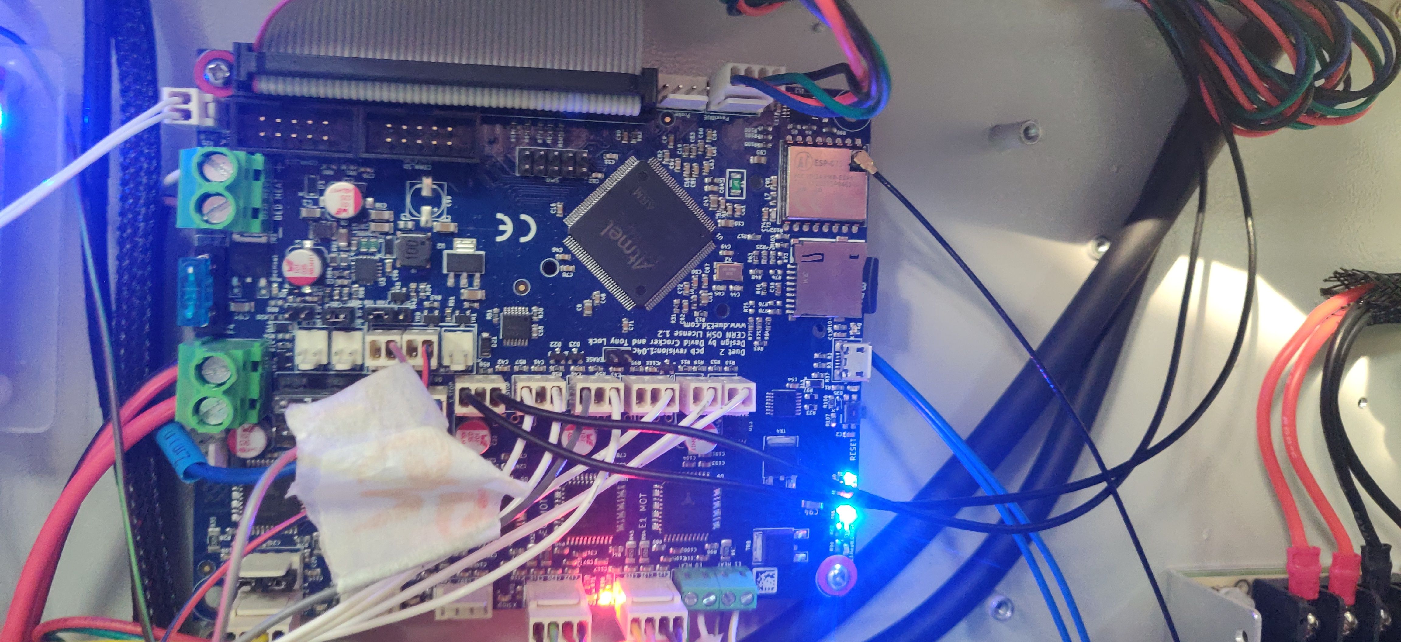
        I completed all the information, thank you again for your reply.

        config.g

        FIRMWARE_NAME: RepRapFirmware for Duet 2 WiFi/Ethernet FIRMWARE_VERSION: 3.3 ELECTRONICS: Duet WiFi 1.02 or later FIRMWARE_DATE: 2021-06-15 21:45:03

        X uses E2 (DRIVE 5), Y uses E3 (DRIVE 6)

        JSS57P integrated digital hybrid servo.pdf

        1 Reply Last reply Reply Quote 0
        • undefined
          Eaton Ren @droftarts
          last edited by 17 Nov 2021, 01:05

          @droftarts

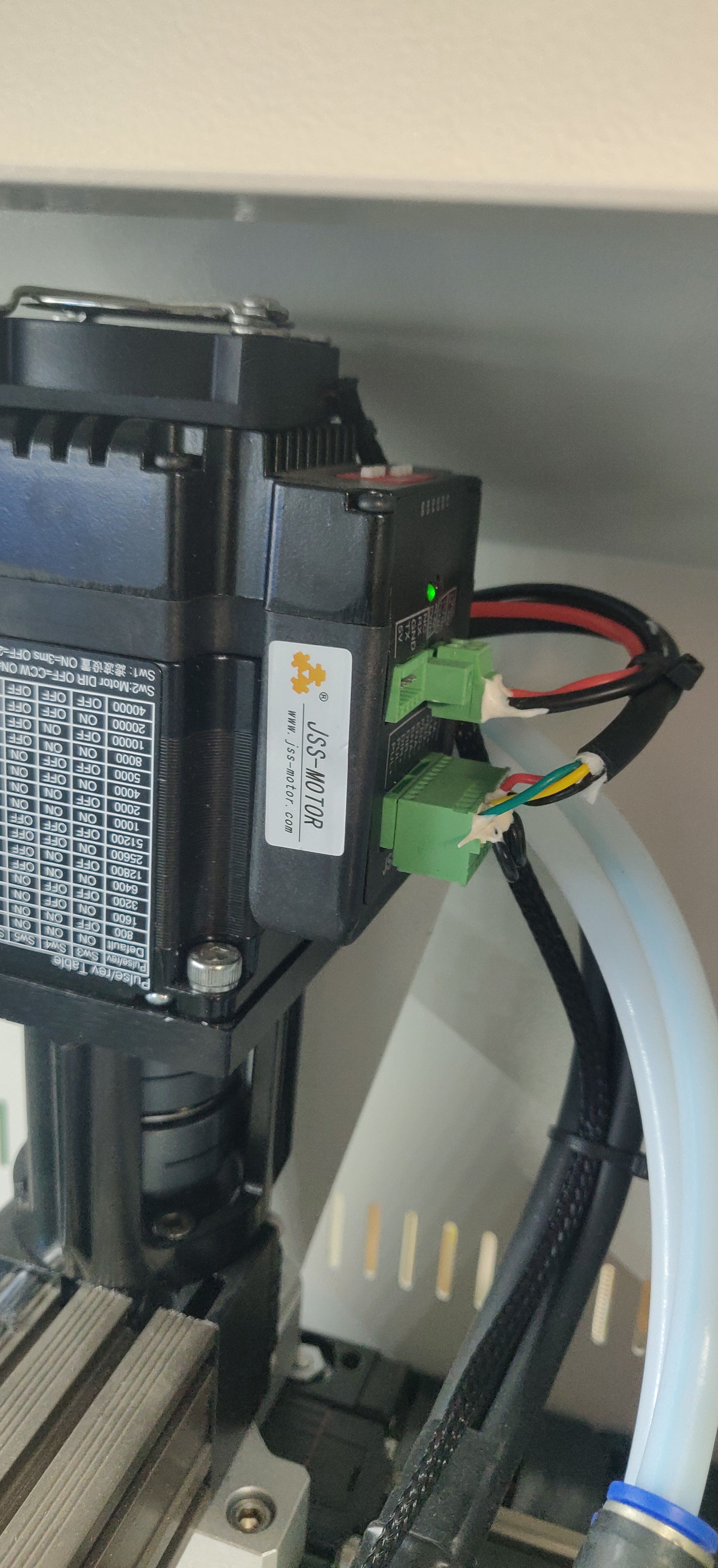
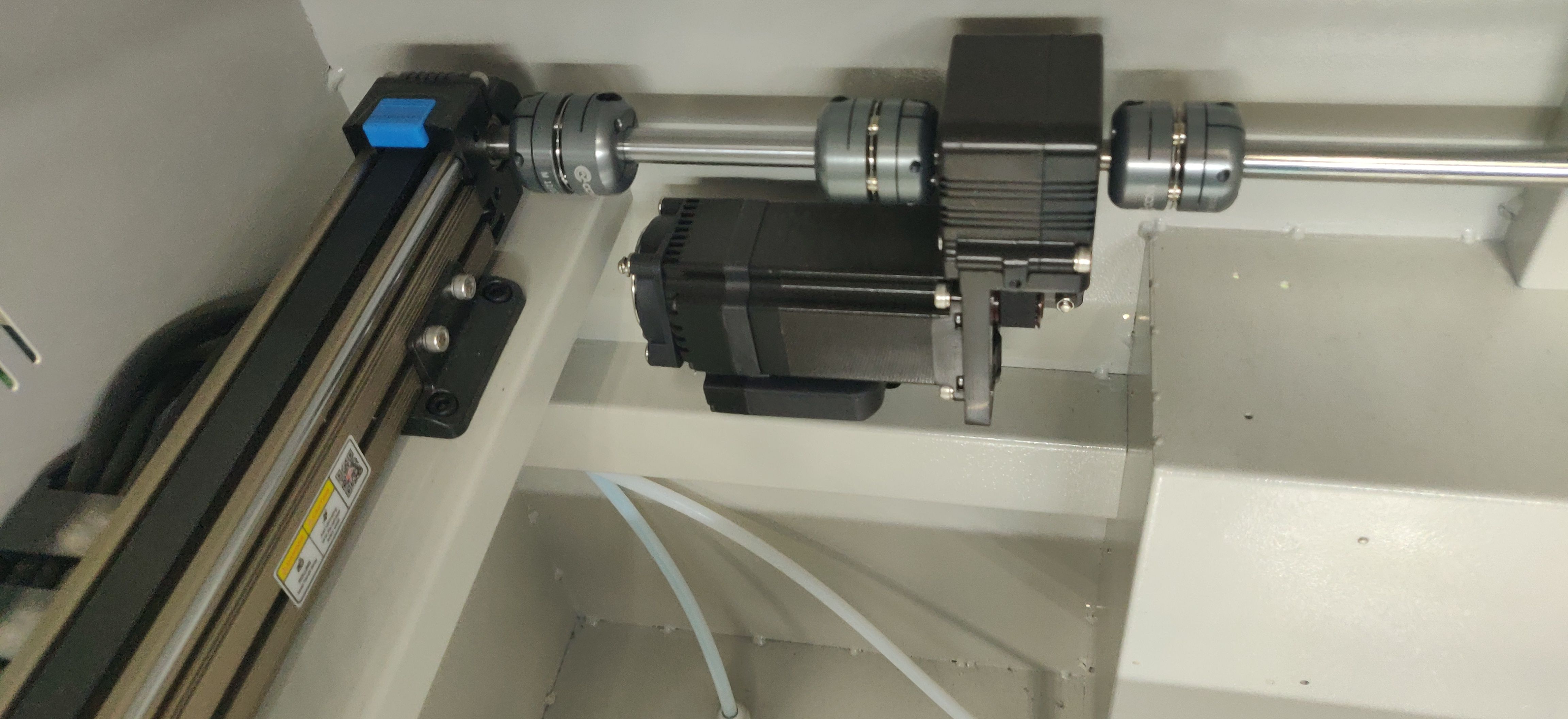
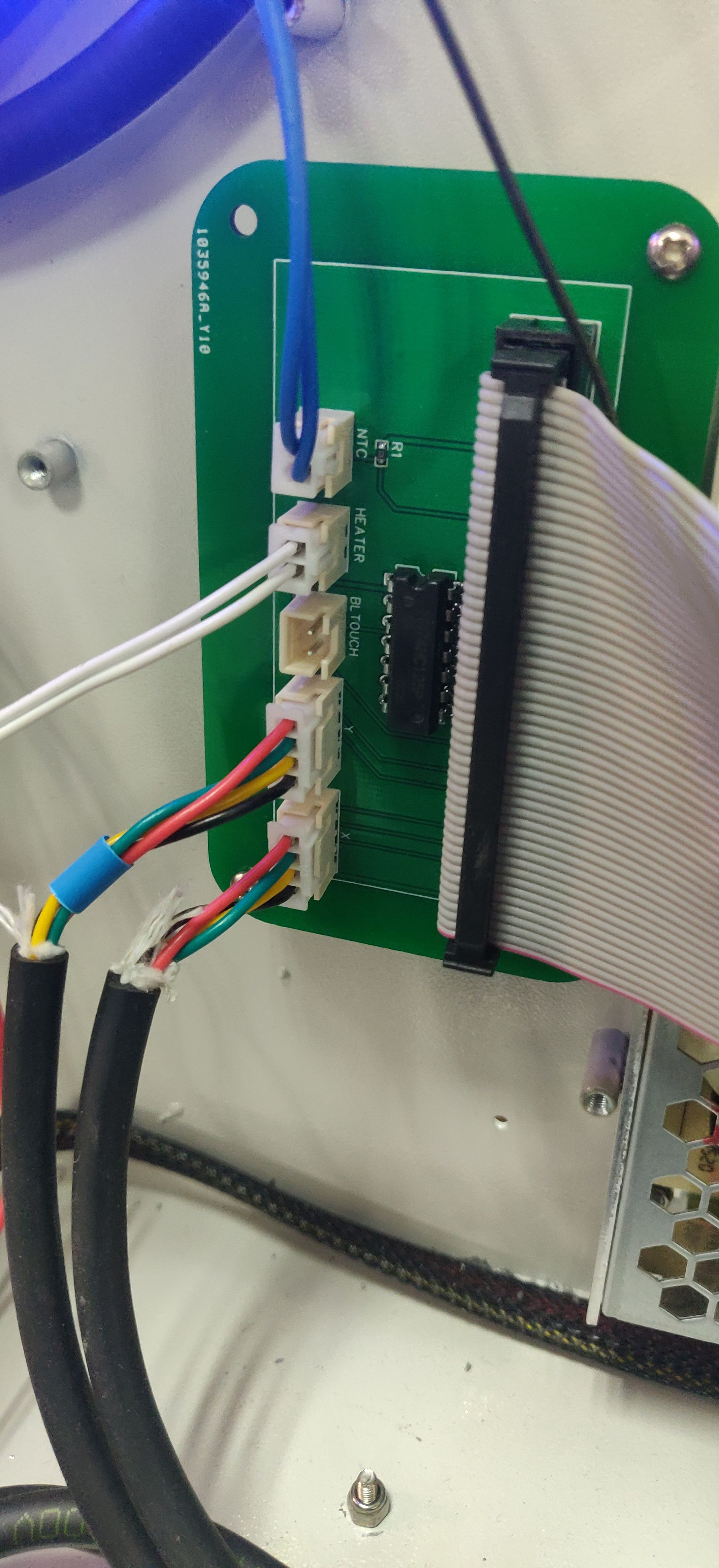
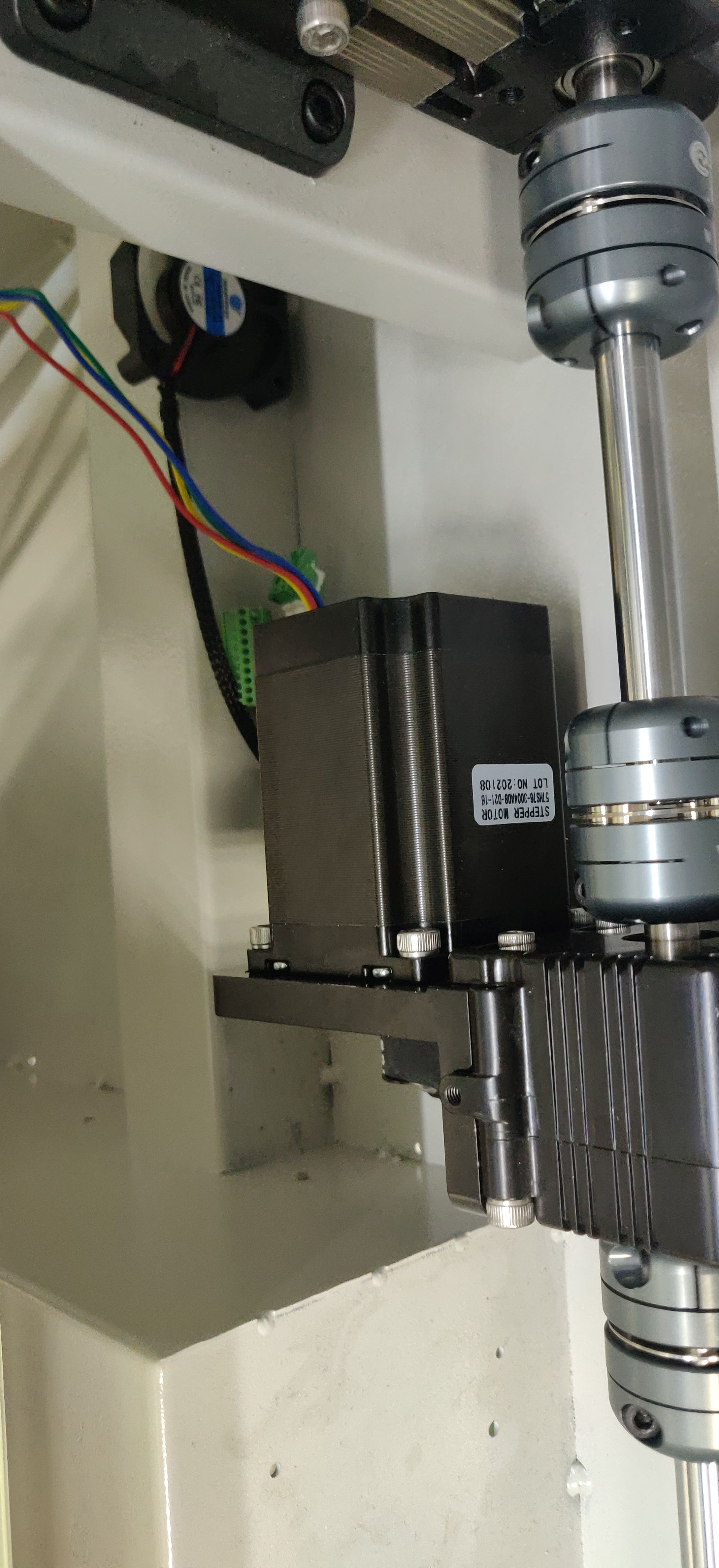
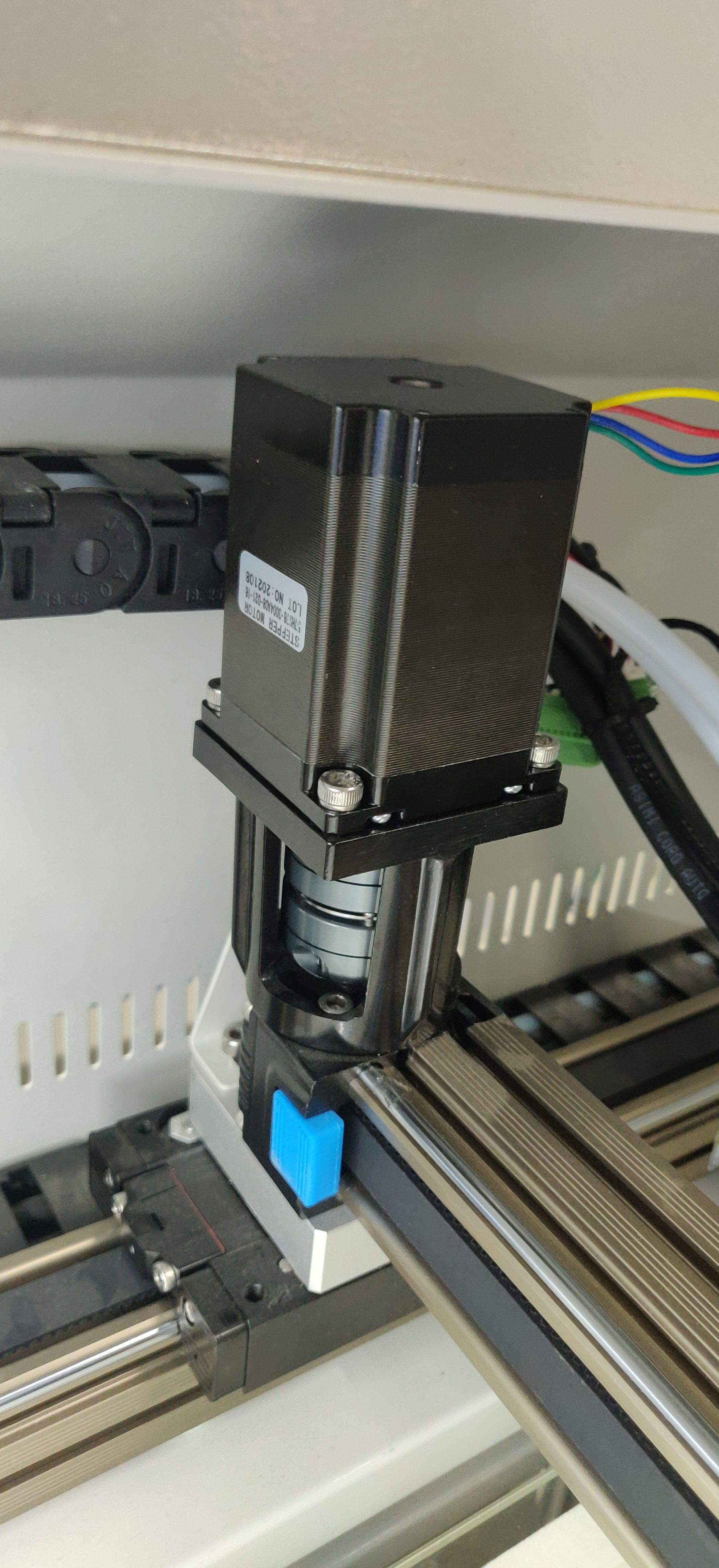
          I added pictures of the wiring.
          I designed an adapter board to facilitate the access of the motor signal line. The motor uses the common cathode connection method.
          X motor subdivision value 8000X motor.jpg
          Y motor subdivision value 20000Y motor.jpg mainboard.jpg adapter PCB.jpg

          1 Reply Last reply Reply Quote 0
          • undefined
            Eaton Ren @droftarts
            last edited by 17 Nov 2021, 02:58

            @droftarts

            Today I use an oscilloscope to observe the pulse signal. It is found that there will be a pulse signal 50ms after the DIR signal. 50ms is too long, I wonder if this is the problem.

            Signal test.png

            undefined 1 Reply Last reply 17 Nov 2021, 17:05 Reply Quote 0
            • undefined
              mrehorstdmd @Eaton Ren
              last edited by 17 Nov 2021, 17:05

              @eaton-ren You have direction hold time set to zero- that's not likely to work.

              I use iHSV servomotors in my sand table and have the timing set up like this:

              M569 P5 S1 R0 T4.0:5.0:6.0:12.0 ; drive 5 reverse, lo enable, timing parameters for servomotors
              M569 P6 S1 R0 T4.0:5.0:6.0:12.0 ; drive 6 reverse, lo enable, timing parameters for servomotors

              I'd bet they're using similar or even identical drivers in your motors and mine.

              I run these motors at 10k acceleration with speeds up to 1600 mm/sec with those timing parameters.

              https://drmrehorst.blogspot.com/

              undefined 1 Reply Last reply 18 Nov 2021, 07:52 Reply Quote 2
              • undefined
                Eaton Ren @mrehorstdmd
                last edited by 18 Nov 2021, 07:52

                @mrehorstdmd Thanks for the help, I tried your T parameter and it didn't work. My client is very anxious, I can only use stepper motors. Today I changed them and used the default port. hope everything is fine.IMG_20211118_154416.jpg IMG_20211118_154424.jpg

                undefined 1 Reply Last reply 18 Nov 2021, 13:22 Reply Quote 0
                • undefined
                  mrehorstdmd @Eaton Ren
                  last edited by mrehorstdmd 18 Nov 2021, 13:22

                  @eaton-ren Maybe the problem is the voltage level on the step/dir/enable lines. I wired the step/dir/enable directly to the corresponding + and - step/dir/enable outputs on a Duet2 expansion board.

                  alt text

                  I did not use the alarm output...

                  https://drmrehorst.blogspot.com/

                  undefined 1 Reply Last reply 20 Nov 2021, 02:01 Reply Quote -1
                  • undefined
                    Eaton Ren @mrehorstdmd
                    last edited by 20 Nov 2021, 02:01

                    @mrehorstdmd said in How to configure the closed-loop motor on duet 2:

                    I did not use the alarm output...

                    After replacing the stepper motors, they worked perfectly. Soon I can deliver two printers to customers.
                    I hope the TMC2660 drive is stable, because I saw a layer shift yesterday.

                    IMG_20211118_163049.jpg
                    IMG_20211119_091212.jpg

                    1 Reply Last reply Reply Quote 0
                    • undefined Shoki referenced this topic 4 Nov 2022, 07:41
                    9 out of 9
                    • First post
                      9/9
                      Last post
                    Unless otherwise noted, all forum content is licensed under CC-BY-SA