Heightmap is completely ignored
-
Good evening,
I am completely helpless. I am trying to get my caribou duet working. This prusa style printer is equipped with a BLTouch-Sensor.
As stated in the headline whilst printing the heightmap is ignored.
Entering M122 while printing the printer says mesh is enabled.
My first layer is definitely printed without any mesh compensation (visible).What I already tried:
- delete heightmap.csv --> printer generates a similarly looking new one (measuring with bltouch works fine) --> firstlayer is not constant
- change the values of heightmap.csv --> the print looks the same as before
- decreasing the measuring points from 7 --> 2 No effect on Printer --> first layer looks just like before
- Using G29 S2 turning off the Mesh Compensation (checked with M122) --> Same first layer as always
- I use two z-Motors. When I turn off the printer and tilt the gantry slightly --> G32 (bed.g) the deviation is corrected by the printer
- using the tapered compensation makes no difference
- allowing the printer to go below z=0 does not affect the first layer
I have absolutely no further clue what could be the possible reason for my printer not to use the heightmap and compensate my printing bed.
Thank you for your help in advance!
Required files are attached.DWC3.3
Board: Duet 2 WiFi (2WiFi)
Firmware: RepRapFirmware for Duet 2 WiFi/Ethernet 3.3 (2021-06-15)
Duet WiFi Server Version: 1.26start.txt PrusaSlicer-StartScript.txt homez.g heightmap.txt config.g bed.g
-
if result > 1                                              ; If the file doesn't exist, perform mesh and save.
   G29                                                     ; Perform mesh now.
   G29 S3 [P{"0:/filaments/" ^ move.extruders[0].filament ^ "/heightmap.csv"}] ; Save heightmap.csv to filament type's directory.
Is this perhaps tripping it up?
Can you share an image of what your heightmap display looks like?
Can you share the first 50 lines or so of a sliced gcode file?
-
allowing "G29 S0" always worked fine for me...
-
Thank you for your help!
The start.g attached to my first post is from a friend of mine. He owns the same printer. It is working for him. When I apply the following start.g (the "official" from caribou3d) the first layer is the same:
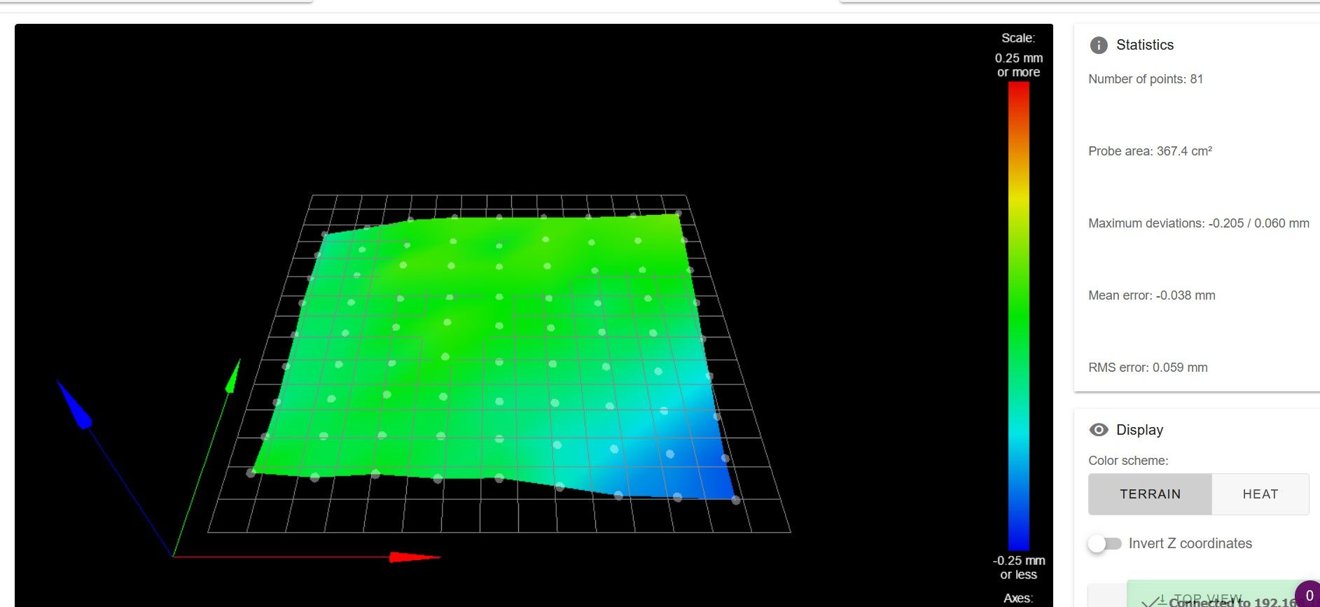
Picture of my heightmap.csv in the systemsfolder (9x9):
gcode-file I try to print (same result when I use prusa slicer 2.3):
; generated by PrusaSlicer 2.4.0+win64 on 2021-12-30 at 16:47:56 UTC
;
; external perimeters extrusion width = 0.60mm
; perimeters extrusion width = 0.50mm
; infill extrusion width = 0.50mm
; solid infill extrusion width = 0.50mm
; top infill extrusion width = 0.45mm
; first layer extrusion width = 0.42mmM107
;TYPE:Custom
; =========================================================================================================
;
; start script for PrusaSlicer for CaribouDuet
;
; =========================================================================================================
;
G28 ; home all axis without mesh bed level
G0 X60 Y-3 Z80 ; move extruder above bed, keep extruder in front for cleaning and checking
;
M104 S160 T0 ; pre-heat extruder to 160°C
M140 S60 ; this will take the layer 1 temperature for bed 0
M190 S60 ; wait for bed temp
;
G29 ; mesh bed leveling using defined mesh grid
G0 X0 Y-3 Z0.6 ; go outside print area
;
M104 S215 ; set extruder temperature
M109 S215 ; wait for extruder temp
;
; =========================================================================================================
;
;
M98 P"0:/sys/primeLine.g" ; execute primeline macro
;
G92 E0.0 ; set extruder position
;
M572 D0 S0.07 ; set pressure advance
;
; =========================================================================================================
G21 ; set units to millimeters
G90 ; use absolute coordinates
M83 ; use relative distances for extrusion
M900 K0.05 ; Filament gcode LA 1.5
M900 K30 ; Filament gcode LA 1.0
M107
;LAYER_CHANGE
;Z:0.2
;HEIGHT:0.2
;BEFORE_LAYER_CHANGE
G92 E0.0
;0.2G1 E-.4 F2100
G1 Z.4 F10800
;AFTER_LAYER_CHANGE
;0.2
G1 X4.516 Y7.168
G1 Z.2
G1 E.4 F2100
M204 P1000
;TYPE:Skirt/Brim
;WIDTH:0.42
G1 F1200
G1 X5.452 Y6.976 E.02998
G1 X245.296 Y6.928 E7.52013
G1 X246.603 Y7.32 E.04278
G1 X247.48 Y8.365 E.04278
G1 X247.673 Y9.305 E.03008
G1 X247.673 Y49.309 E1.25429
G1 X247.426 Y201.94 E4.78564
G1 X247.032 Y203.246 E.04278
G1 X245.985 Y204.121 E.04278
G1 X245.051 Y204.313 E.0299
G1 X5.274 Y204.483 E7.51806
G1 X3.967 Y204.092 E.04278
G1 X3.09 Y203.046 E.04278
G1 X2.896 Y202.106 E.03008
G1 X3.076 Y9.35 E6.04373
G1 X3.469 Y8.044 E.04278
G1 X4.47 Y7.207 E.0409
; printing object Form-Kubus id:0 copy 3for my taste (taste because I am a noob and have no knowledge
 ) the g29 Sxx is applied a little to often. Is there any known interference?
I have often read that possibly the z-Motors don't get enough voltage for mesh compensation?
I have already checked that my extruder can travel along the gentry easily. A tilt of the gantry can be performed easily by turning one spindle.
I have not found any further (gcode-)commands where the used mesh can be visualised? Is there a way? Or is there a way to easily visualize the motor signals? So that one can see if there is a signal for the motor to turn?...and again thank you for your much appreciated help in advance!
-
I did not understand did using G29 S0 solve the problem?
For some time I think my meshlevel is doing nothing , but as far my deviation is about 0.08 to 0.12 on 550 x 450 bed I do not have fails .
My Gcode is just
G32 - 3 point tramming with 3 Z motors and then G29, during first layer there is some minor difference in line thickness.
Should I use G29 or G29 S0 -
Hello @martin7404,
thank you for your answer.
G29 S0 did not wirk for me. I have just tried to implement it in the Start code in prusa Slicer.
The mesh measuring on all 9x9 points was made according to config.g.
But: the contourline of my print looks as bad as before.
On the left the nozzle is way to close to the bed. On the right there is nearly no contact between the nozzle an the bed.
My bed is too close on the left but too far on the right. So I assume there is absolutely no mesh compensation going on. -
@kevincorinth here is how to check whether mesh bed compensation works without a print:
a) home the printer (G28)
b) edit the heightmap csv to add 1mm to one of the points, ideally to the middle of the bed. Save it as "fakeheightmap.csv")
c) load the edited mesh (G29 S1 P"fakeheightmap.csv")
d) move your print head to X minimum and the Y coordinate of your modified point.
e) Command a G0 move to X maximum at a low speed. You should see the Z spindles moving up and down to accomodate the fake high point. -
Hello @oliof ,
thank you for your beautiful idea!
I modified your idea slightly. Instead of changing only one (of 81) point(s). I changed a complete line.
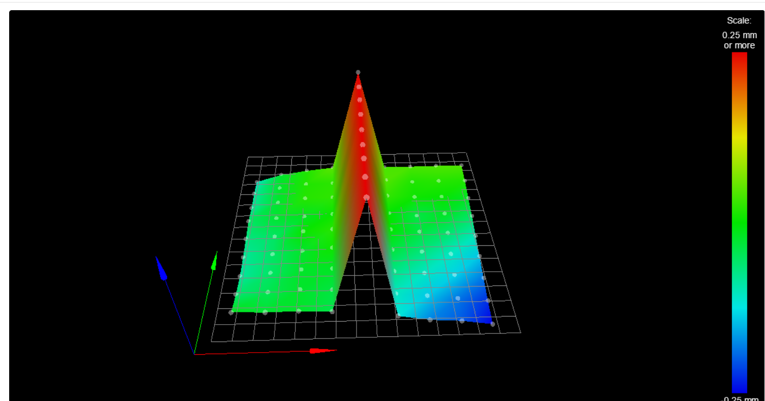
But hooray. This method worked for me. I was able to see the rise and fall of the nozzle in the middle of the bed, where the fakeheightmap.csv was active!
At least I know now that there is some heightmap usage in the Background.
but sadly I still don't know what is wrong with my heightmap.
Could it be a bad offset of my BLTouch?
Or any other guesses?Thank you very much in Advance!
")
-
@kevincorinth i am not near my printers now. I will do folowing:
Home, tram and g29
I have 50 mm height gauge with dial indicator an will check mesh points with it -
So one thing I note is that you save filament specific height maps, but you just load the generic heightmap.csv in the startup gcode @kevincorinth. Does the generic heightmap.csv even exist?
Since you can have filament profile specific gcode in PrusaSlicer which you seem to be using, maybe move the G29 from the startcode there, and reference the filament specific one.
<>RatRig V-Minion Fly Super5Pro RRF<> V-Core 3.1 IDEX k*****r <> RatRig V-Minion SKR 2 Marlin<>
-
also considering your height map image -- that already looks pretty flat. I would print on that without compensation (ignoring the front right corner unless I really have a full plate, which I tend to avoid).
Maybe you can show us a bit more about your setup: Print plate, printer gantry, hotend/nozzle, etc. I am at this point assuming your problem is not one of the heightmap, but another mechanical issue.
<>RatRig V-Minion Fly Super5Pro RRF<> V-Core 3.1 IDEX k*****r <> RatRig V-Minion SKR 2 Marlin<>
-
My first Layer is my USP. And my duet printer is my most expensive one. So achieving a perfect first layer would be great.
yes, there is always a heightmap.csv generated.
I have included in the start gcode of my prusa Slicer following lines:
"
G29 S2 ;clear all stored mesh
G29 S1 P"fakeheightmap.csv ; use the "Faked" heightmap
"
The result has been as expected. In the middle I still have a + 1mm offset in my fakeheightmap.csv. My first Layer looks exactly as usual. But you can see that in the middle the contour line has way less contact to the printsheet as to the right and left.As a result my heightmap.csv is not ignored. My heightmap.csv ist simply too "weak"?
I will try what @martin7404 suggested. I will use a gauge and measure myself to compare the measured values with the BLTouch ones. I hope that helps me to get a clue of what is going wrong here.
Are there any known issues?
Thank you for your help!
-
I had a similar issue with a printer I'm building and the root cause was that when the print head moved from one side of the bed to the other, there was a slight force on it from the wiring and filament. This force caused the printhead to tilt one way on side 1 of the bed and tile the other way on side 2. That tilting lifted the nozzle enough to cause the first layer to not adhere, or shoved the nozzle into the bed. The offset of the z-probe from the nozzle can amplify any wobbliness in the printhead.
-
Thank you very much for your answer.
In deed my extruder was a little bit loose (compared to my einsy prusa extruders). I have completely diassembled my extruder on my caribou duet and retightened all the screws an cables.Now my extuder is mounted rocksolid. But I still have a poor first layer.

-
my setup:
I have assembled the printer myself. The parts are printed by myself.
- I have just disassembled and reassembled my bondtech extruder with Mosquito hotend.
- I have also loosend the rod screws for the gantry. I have heard there can be some mechanical issues.
Still no change.
Thank you for your help in advance.
-
OK, the quick answer did not solve the problem. Putting on my mad scientist thinking cap...
Your original post said you had a bad first layer, so let's keep that as the problem to solve. Several posts and experiments here have shown that the mesh compensation matrix does make the z motors move as the print head moves, so we conclude mesh compensation is "on", but does not seem to be working well.
Theories of what might be wrong:
-
The z-offset between the probe and the nozzle may be different at different points on the bed.
-
Z offset might be set wrong everywhere on the bed.
-
Something else (mad scientist's last excuse).
Now we need to experiments to test our theories.
Some missing data - you didn't explain or show a picture of the bad first layer - is it everywhere, or good in some places and bad in others?
Experiment 1 - Turn off mesh compensation. move the nozzle to the middle of the bed and home Z (G30) there. Now we ignore the rest of the bed and print a 25mm square that is one layer thick. If this layer is not good, adjust the z-offset until it is good. This is now your Z-offset for the next experiments.
Experiment 2 - Move the nozzle near one corner of the bed (where the worst layer 1 is happening). Use G30 to home in that location. Print a single layer 25mm square in this location. If the offset between the nozzle and the probe is consistent in this location, the layer should be as good as in the center of the bed, adding weight to theory 1. If not, this adds weight to Theory 2 above. If the first layer looks bad, note whether it's too thin (nozzle too low) or too thick (nozzle too high).
Experiment 3 - If experiment 2 gave a bad first layer, let's see if the error is consistent on the other corners of the bed. If you got a good print in experiment 2, I'd skip this experiment. Repeat experiment 2 on those corners (move nozzle to a corner, home (G30) there, print small square. Look for changes in the quality at each corner. Does it change? How? I looked at the pictures on the caribou web page and they don't show the location of the tough probe, but the Superpinda looks to be to the right of the nozzle, but close to the nozzle front/rear. If the badness of the first layer on the left sides are the same but opposite of the badness on the right side, I'd add more weight to theory 2. If the front corners are the same badness but opposite to the rear corners, I'd give less weight to theory 2. If diagonal corners are equal badness, but opposite to the badness of the other diagonals, I'd just to theory 3 - something else and that something would be that the 4 leveling screws are curving the bed. The height map you posted shows this, but the amount of height offset seems low enough that mesh compensation should remove it.
Experiment 4 - do this if Experiment 2 made a good first layer. We are pursuing theory 1 now, and we think that we have a good Z-offset. Run bed leveling and compensation, then print a 25mm square near each corner of the bed. Are they all good now? If not, what is the quality of the first layers? Note that this experiment is different from experiment 2 because Z is not re-homed near each corner.
Hopefully these experiments will give you some insight to what is happening, and hopefully a simple z offset adjustment will solve it. If you are still on the path of theory 2, I'd sit in front of the machine with your experiment 3 results and ask "what could be causing the probe offset to change in a way that would give these results?". When I had a similar problem, here's where I ended up at this step. It's not your printer, but the pictures might give you some ideas of what to think about if you are staring at your printer and asking "how are you doing this to me?" https://forum.duet3d.com/topic/26397/mesh-compensation-effect-on-g30-command
In a worst case scenario, you could do an experiment 5 where you readjust the zoffset at each corner (maybe 5 x 5 mesh points) and capture the offset differences. Then compare to the heightmap.csv at those points. The difference would be a "machine adjustment for whatever is happening we can't figure out". Then you could write a macro that added those adjustments to the heightmap and applied it. This would be a brute force method and might need to be repeated occasionally.
-
-
I finally found time to do your very helpful scientific experiment.
Was to complicated for me.
But for anyone else having this problem:
My z axis minimum was set to z0
Changing M208 for Z0 to Z-2 in config.g was finally solving the problem.
@atall thank you all for your great and quick help, tips and tricks.
After 10 months of guessing and time consumable troubleshooting I am finally able to use my most expensive printer!
hooray!