No tools are showing in DWC - noob
-
@phaedrux This is what M98 said
M98 P"config.g"
HTTP is enabled on port 80
FTP is disabled
TELNET is disabled
Error: in file macro line 131 column 38: M563: expected number after 'F'
Error: Tool 0 not found
Error: Tool 0 not found
Error: in file macro line 137 column 40: M563: expected number after 'F'
Error: Tool 1 not found
Error: Tool 1 not found
Warning: Macro file config-override.g not found -
; Tools
M563 P0 S"extruder 0 (model)" D0 H0 F-1 ; define tool 0
G10 P0 X0 Y0 Z0 ; set tool 0 axis offsets
G10 P0 R0 S0 ; set initial tool 0 active and standby temperatures to 0C
M563 P1 S"extruder 1 (support)" D1 H1 F-1 ; define tool 1
G10 P1 X0 Y0 Z0 ; set tool 1 axis offsets
G10 P1 R0 S0 ; set initial tool 1 active and standby temperatures to 0C
Can you try mofifying your tool definition to look like
; Tools
M563 P0 S"extruder0" D0 H0 ; define tool 0
G10 P0 X0 Y0 Z0 ; set tool 0 axis offsets
G10 P0 R0 S0 ; set initial tool 0 active and standby temperatures to 0C
M563 P1 S"extruder1" D1 H1 ; define tool 1
G10 P1 X0 Y0 Z0 ; set tool 1 axis offsets
G10 P1 R0 S0 ; set initial tool 1 active and standby temperatures to 0C
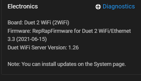
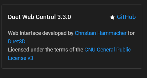
Can you also check the settings tab in DWC and verify the version matches 3.3
-
@phaedrux I didn't see a settings tab but these are from elsewhere in DWC:
-
@phaedrux Ok made the changes to the tool section and now they are showing up in DWC and on the PanelDue. Thank you very much!
However when I touch the heater 1 icon I get : Error Temperature reading fault on heater 1: sensor open circuit
I double checked the wiring and the thermistors are connected to E0 temp and E1 temp.
One thing to note and I'm not certain this is an issue, I have a breakout board on the extruder body for all the wiring so that I can just plug one 25pin plug into it to swap out extruders. I've double checked the wiring to make sure everything is going where it should.
Thanks again for your help on this!
-
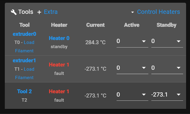
@phaedrux Odd, its now showing two extruders in tool 1 with two heaters and a third heater in tool 2.
-
@nvigr8 said in No tools are showing in DWC - noob:
One thing to note and I'm not certain this is an issue, I have a breakout board on the extruder body for all the wiring so that I can just plug one 25pin plug into it to swap out extruders. I've double checked the wiring to make sure everything is going where it should.
Do you have a wiring diagram for this board?
I would suggest testing the wiring direct to remove the breakout board from the equation. It may be sharing a negative ground connection that the duet uses to switch the heater.
-
@phaedrux To what do I set the active and standby temps? Would you please explain them?
I wired in an extra thermistor directly to the board and did not get the error this time. It reads a normal temp on DWC but on the PanelDue it still reads a crazy number. Also even though I don't have a heated bed in the configuration, it shows one on the Panel Due.
I'll have to draw a diagram for you tonight or tomorrow. I would really like to be able to use this breakout board setup. I have three different extruder assemblies that I will be switching between and it will make the switch so much easier.
Thanks for your help.
-
You probably need to update your paneldue firmware
https://duet3d.dozuki.com/Wiki/PanelDue_Firmware_update
@nvigr8 said in No tools are showing in DWC - noob:
To what do I set the active and standby temps? Would you please explain them?
Normally they would be set by your slicer.
-
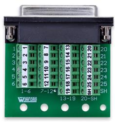
@phaedrux This is the breakout board that I'm using:
Here is a diagram:
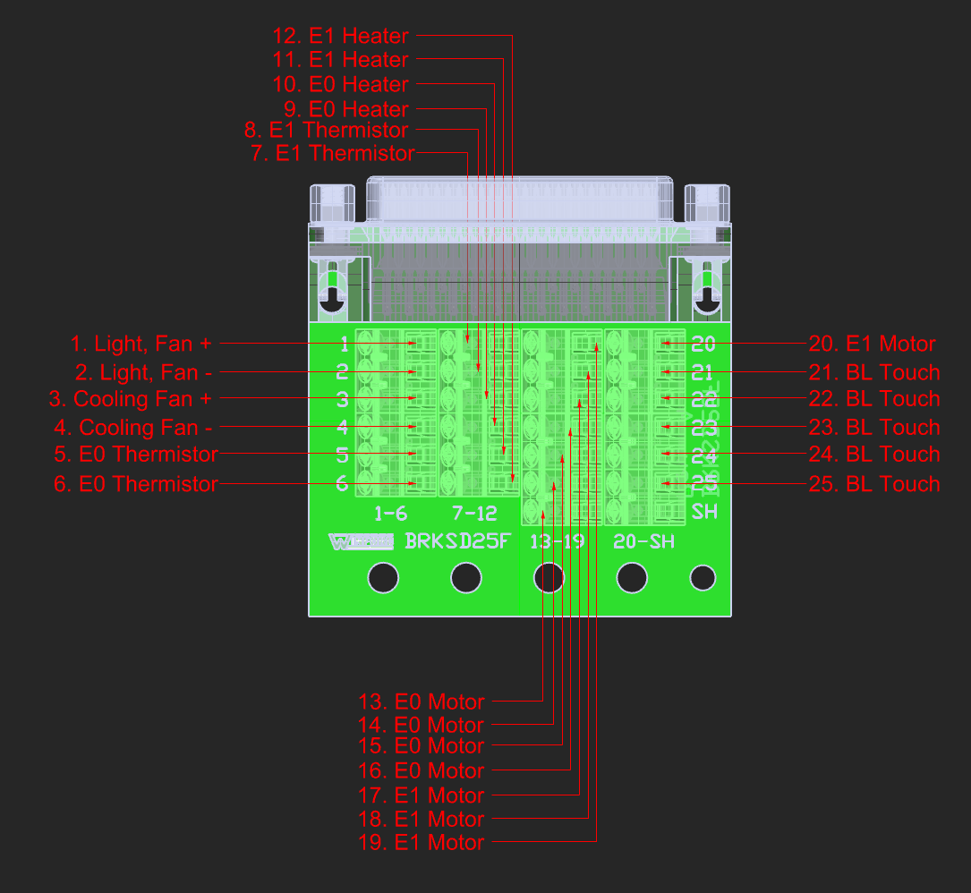
Note: This assembly does not thave E1 and accessories. Connections are there for another two extruder assembly.Here is the corresponding plug pins:
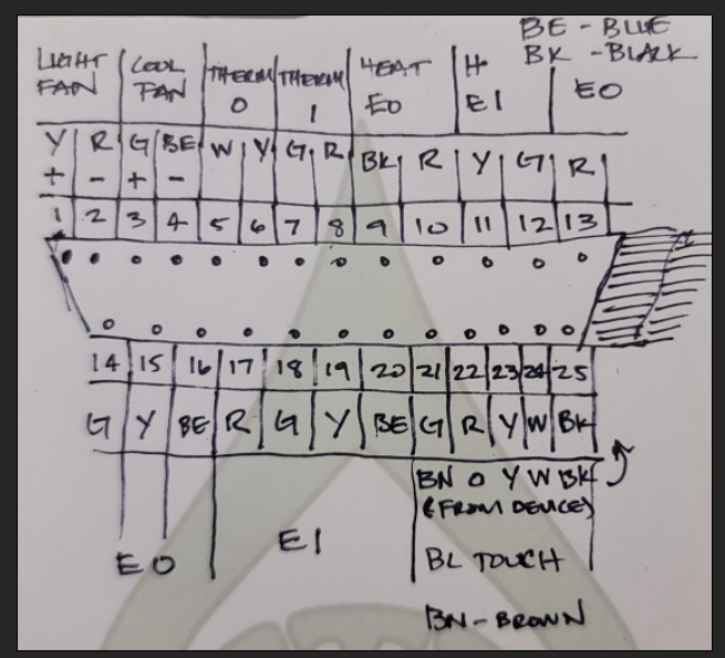
Pic of the whole assembly:
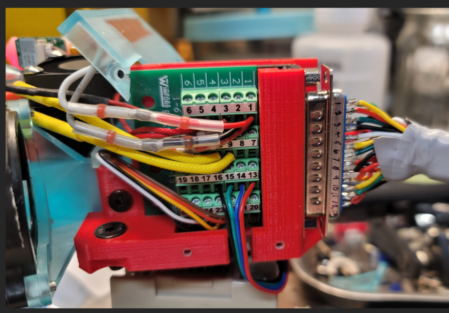
One thing that just occured to me, does soldering thermistor wires cause problems?
Thanks.
-
@phaedrux Do you know what the SH terminal on that breakout board is for?
Also, after doing some reading, it looks like I should have checked the resistance on the wires I used to connect the thermistors... Maybe that is part of the issue. Tonight I'll replace those cables with thermistor cables and crimp them onto the plug pin instead of soldering.
-
@nvigr8 Change the S1 to S0 in your M574.
-
@stephen6309 Thank you for the input. Last night I finally got the X and Y endstops and movement working properly.
However, now the Z endstop shows as being on even though the BLtouch has not been triggered. Not sure what I changed to make this happen.
-
-
@stephen6309 Which .g file would that be in? Thanks.
-
@stephen6309 NM, I found it. Thanks! I'll try it out at lunch.
-
@nvigr8 config.g You just need to edit the one in there already.
-
@stephen6309 What does that ! do there to make it work?
-
@nvigr8 The ! inverts the signal from the pin.
-
@stephen6309 Ah, good to know. Thank you.
-
@stephen6309 Thanks again for the help. However, when I first made this post and put in the config.g it WAS working. It was the ONLY axis working at the time. In trying to fix other problems - tools, thermistors, etc. I must have changed something to make it not work. That line you referenced earlier apparently didn't change though.
I just wanted to give a little more context. I will still try your suggestion when I go home for lunch.
; Configuration file for Duet WiFi (firmware version 3.3)
; executed by the firmware on start-up
;
; generated by RepRapFirmware Configuration Tool v3.3.10 on Wed Jan 05 2022 21:06:25 GMT-0600 (Central Standard Time)

; General preferences
M575 P1 S1 B57600                                      ; enable support for PanelDue
G90                                                    ; send absolute coordinates...
M83                                                    ; ...but relative extruder moves
M550 P"Multoo"                                         ; set printer name

; Network
M552 S1                                                ; enable network
M586 P0 S1                                             ; enable HTTP
M586 P1 S0                                             ; disable FTP
M586 P2 S0                                             ; disable Telnet

; Drives
M569 P0 S0                                             ; physical drive 0 goes backwards
M569 P1 S0                                             ; physical drive 1 goes backwards
M569 P2 S1                                             ; physical drive 2 goes forwards
M569 P3 S1                                             ; physical drive 3 goes forwards
M569 P4 S1                                             ; physical drive 4 goes forwards
M584 X0 Y1 Z2 E3:4                                     ; set drive mapping
M350 X16 Y16 Z16 E16:16 I1                             ; configure microstepping with interpolation
M92 X80.00 Y80.00 Z400.00 E400.00:400.00               ; set steps per mm
M566 X900.00 Y900.00 Z60.00 E120.00:120.00             ; set maximum instantaneous speed changes (mm/min)
M203 X6000.00 Y6000.00 Z180.00 E2100.00:2100.00        ; set maximum speeds (mm/min)
M201 X500.00 Y500.00 Z20.00 E250.00:250.00             ; set accelerations (mm/s^2)
M906 X1300 Y1300 Z1300 E450:450 I30                    ; set motor currents (mA) and motor idle factor in per cent
M84 S30                                                ; Set idle timeout

; Axis Limits
M208 X0 Y0 Z0 S1                                       ; set axis minima
M208 X420 Y410 Z470 S0                                 ; set axis maxima

; Endstops
M574 X1 S1 P"!xstop"                                   ; configure switch-type (e.g. microswitch) endstop for low end on X via pin !xstop
M574 Y1 S1 P"!ystop"                                   ; configure switch-type (e.g. microswitch) endstop for low end on Y via pin !ystop
M574 Z2 S2                                             ; configure Z-probe endstop for high end on Z

; Z-Probe
M950 S0 C"exp.heater3"                                 ; create servo pin 0 for BLTouch
M558 P9 C"^zprobe.in" H5 F120 T6000                    ; set Z probe type to bltouch and the dive height + speeds
M558 H30                                               ;*** Remove this line after delta calibration has been done and new delta parameters have been saved
G31 P500 X-32.69 Y-31.88 Z2.5                          ; set Z probe trigger value, offset and trigger height
M557 X15:215 Y15:195 S20                               ; define mesh grid

; Heaters
M308 S0 P"bedtemp" Y"thermistor" T100000 B3950         ; configure sensor 0 as thermistor on pin bedtemp
M950 H0 C"bedheat" T0                                  ; create bed heater output on bedheat and map it to sensor 0
M307 H0 B1 S1.00                                       ; enable bang-bang mode for the bed heater and set PWM limit
M140 H0                                                ; map heated bed to heater 0
M143 H0 S120                                           ; set temperature limit for heater 0 to 120C
M308 S1 P"e0temp" Y"thermistor" T100000 B4725 C7.06e-8 ; configure sensor 1 as thermistor on pin e0temp
M950 H1 C"e0heat" T1                                   ; create nozzle heater output on e0heat and map it to sensor 1
M307 H1 B0 S1.00                                       ; disable bang-bang mode for heater  and set PWM limit
M143 H1 S295                                           ; set temperature limit for heater 1 to 295C
M308 S2 P"e1temp" Y"thermistor" T100000 B4725 C7.06e-8 ; configure sensor 2 as thermistor on pin e1temp
M950 H2 C"e1heat" T2                                   ; create nozzle heater output on e1heat and map it to sensor 2
M307 H2 B0 S1.00                                       ; disable bang-bang mode for heater  and set PWM limit
M143 H2 S295                                           ; set temperature limit for heater 2 to 295C

; Fans
M950 F0 C"fan0" Q500                                   ; create fan 0 on pin fan0 and set its frequency
M106 P0 S0 H-1                                         ; set fan 0 value. Thermostatic control is turned off
M950 F1 C"fan1" Q500                                   ; create fan 1 on pin fan1 and set its frequency
M106 P1 S1 H1:2 T45                                    ; set fan 1 value. Thermostatic control is turned on

; Tools
M563 P0 D0 H1 F0                                       ; define tool 0
G10 P0 X0 Y0 Z0                                        ; set tool 0 axis offsets
G10 P0 R0 S0                                           ; set initial tool 0 active and standby temperatures to 0C
M563 P1 D1 H2 F0                                       ; define tool 1
G10 P1 X0 Y0 Z0                                        ; set tool 1 axis offsets
G10 P1 R0 S0                                           ; set initial tool 1 active and standby temperatures to 0C

; Custom settings
; add for filament sensors
M591 P1 C"e0stop" S1 D0                                ;filament monitor connected to E0 endstop
M591 P1 C"e1stop" S1 D1                                ;filament monitor connected to E1 endstop


; Miscellaneous
M911 S10 R11 P"M913 X0 Y0 G91 M83 G1 Z3 E-5 F1000"     ; set voltage thresholds and actions to run on power loss
T0                                                     ; select first tool
