How corexy belts tension?
-
@mikeabuilder Is that on the extruder carriage? It's very elaborate (that's good in a sort of steam-punk way), but seems like a lot of extra weight to carry around for the purpose of tightening the belt, which you'll probably do only one time. I prefer to tension belts on a fixed part of the printer, with simple screws holding them in place. Specifically, sliding motor mounts with screws in slots to allow positioning of the motors along the Y axis. The ends of the belts clamp at the extruder carriage. The motor mounts had to be screwed down anyway, so simply cutting slots for those screws solves the belt tensioning problem. Adjustments can be made without affecting the parallel relationship of the belt and the Y axis guide rail.

The linked post was my failed clamp design. It might have worked OK for glass/aramid core belts, but it sure didn't work for steel core. This is what I use to anchor the belts at the extruder carriage- it's all a little bigger than I'd like, but it's working and I have other projects to work on and limited time.
I could reduce the weight and probably improve reliability if I just cut a couple slots in the aluminum body of the extruder carriage, fold the belts over steel pins and back through the slots, and secure the ends with zip ties. Maybe someday.
-
@mrehorstdmd, yes all that stuff is on the extruder carriage. I'll take the steampunk comment as a compliment. And it did add a lot of mass (the guitar tuner is fitted to a small bronze casting) but we're using NEMA23 motors and hope all will be well - testing at the makerspace is delayed by omicron. Meanwhile my second design is progressing in my home workshop and it's much more compact, including getting the tensioners off the carriage.
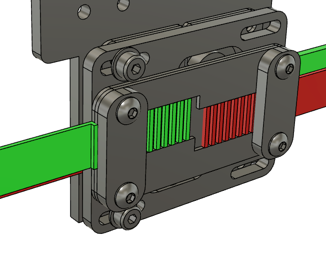
In my new design, I've done a lot of work to get the belts really close to each other at the carriage, both in Z (7mm overlap) and Y (3mm spacing). The fixed ends are clamped first to the carriage using a stack of 1mm aluminum plates and a 3mm clamp.
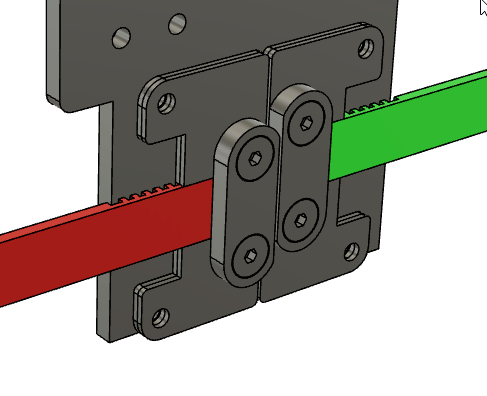
The floating ends of the belt are connected to a 3mm plate that can slide side to side, this is required to make the "one belt".
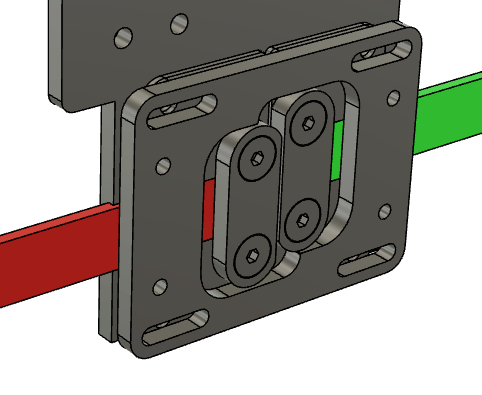
The other ends of the belt are then clamped to this floating plate.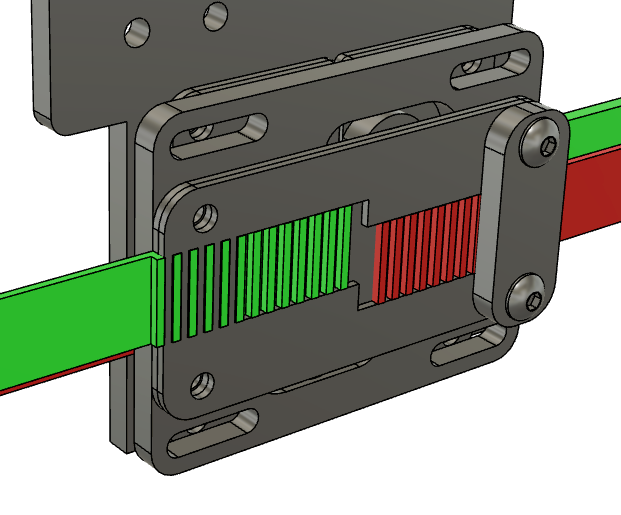
After the "one belt" is tensioned, the sliding motion is lockedby 4 cap screws (only two shown).
Ofcourse, if the belt teeth get ripped off the belts, as @rjenkinsgb points out, I'll be back to the drawing board.
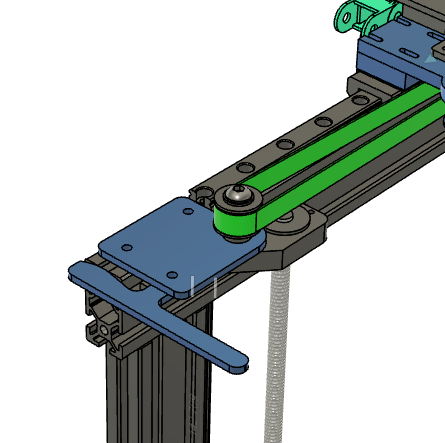
I'm tensioning the belts where the front pulley plates lock into my 2040 extrusions. I even added a lever in case I want to get crazy.
I also pack an extruder, mosquito hot end, part cooling fan, and BLtouch probe onto the carriage.
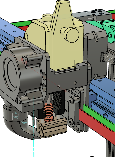
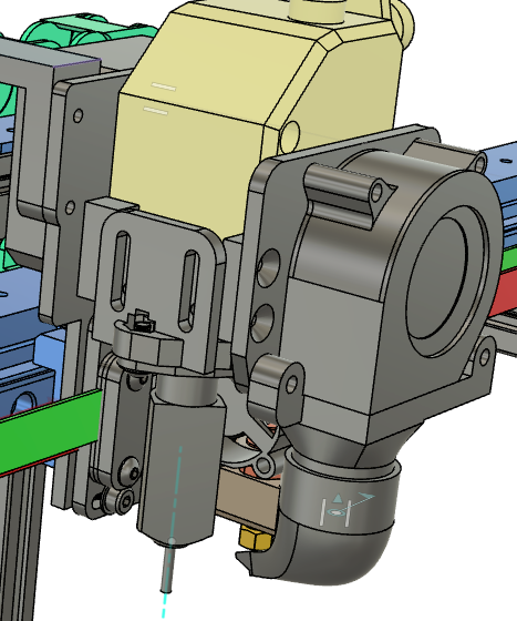
Ten pounds of shit in a 5 pound bag. -
@mikeabuilder Interesting. I'm trying to figure out what the corner pulleys look like with a 7mm overlap of the belts.
-
Mine uses a rather different anchor system:
The first two photos are of some prototype parts:
The belts run through curved channels which take them across the back of the clamping pockets. There are short offcuts of belt glued in the back to add friction and elasticity to the clamp force.The clamp blocks are serrated and the final ones have stepped sides to reduce the twist in the pockets, caused by the belt tension.
The third photo is the final head assembly on the working machine; the belts are cut short at the far end but left with tails at this end to allow enough to grip for easier pre-tensioning.


-
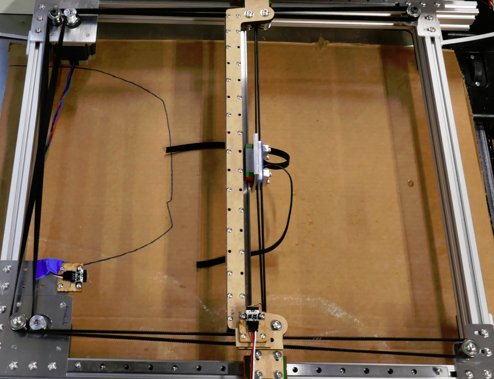
@mrehorstdmd, another one of my possibly stupid ideas with this printer is the use of a twisted belt configuration at the belt crossing. Here's the prototype I made to test the belt twist. It worked well except that the laser cut mdf bridge could not keep the pulley axles straight. I'm just getting ready to buy aluminum parts
I don't have a good photo, but the CAD model shows the two motor gear and rear corner idler.
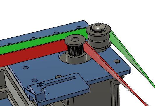
To make it work, I'm using a pair of flanged bearings as the idler and they have a bigger diameter than the drive gear on the NEMA23 motor. To make the twisted belts pass without hitting each other, the idler and gear axes need to be aligned. And you can see that without the two diameters, I'd need another idler to get the belt past the drive gear.
-
@mikeabuilder Your motors are only engaging the belt at a 90 degree wrap. That's potentially going to let the belt slip, and is liable to be pretty noisy as the belt teeth meet the pulley. OTOH, the corners on the right wrap around the pulleys at 180 degrees. That would be a better place for the motors.
It looks like there are twists in both belts at the motor mount, and one of them is going to be in the variable length segment between the drive pulley and the X axis pulley block. That means as the X axis gets closer to the drive pulley (Y max or Ymin) the belt is going to have to twist over a shorter and shorter distance which is going to cause problems tracking on the pulleys and probably wearing the belt out quickly, among other potential problems. Belt manufacturers usually have some minimum distance spec for a 90 or 180 degree twist.
The corner pulley on the left in the belt diagram doesn't have to be in line with the drive pulley. If you move it downward in the drawing it will have plenty of clearance.
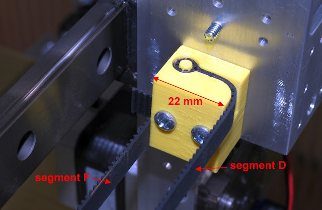
This is mine:
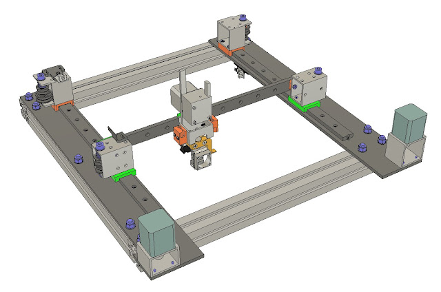
Notice the larger pulley on the bottom of the corner pulley block on the left. That provides extra clearance for the belt as the X axis approaches the corner pulley block. There are no twists in the belts- the pulleys (F608 bearings) are large enough (22 mm dia) that 9 teeth of the belt contact the surface even where the wrap is only 90 degrees (I saw this recommendation in some Gates whitepaper on GT2 belts).
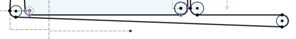
This is the belt diagram of my printer:

Putting at least 9 belt teeth into contact with a smooth pulley avoids print defects, but anytime you have belt teeth contacting pulleys (smooth or toothed), it's going to make "zippy" noises at high speeds (~200 mm/sec and up). If you are concerned about noise, put a single twist in each belt in the outermost segments (J and K in my diagram). After that only the smooth side of the belts will contact the pulleys (except the drive pulley, of course). The two drive pulleys will still make noise, but that's quieter than ten pulleys making zippy noises. If you aren't too concerned about noise and you want to avoid print defects, use larger pulleys made from stacked bearings. Larger bearings, generally, will last longer than smaller bearings, and belts will probably last longer bending around larger pulleys, too. Avoid the little 3D printer pulleys like a case of COVID if you want to get reliable long-term operation. If you want quiet operation and long life, use large bearings for the pulleys and twist the belts as described above.
NEMA-23 motors are usually noisier than NEMA-17 motors, so if you can get a NEMA-17 motor that has sufficient speed/torque, use it.
Avoid adding extra pulleys in the belt paths. Each pulley you bend the belt over increases the load on the motors. That will ultimately limit speed/acceleration because stepper torque drops as speed increases. If you have a corexy printer you can feel the effect- just manually move the X axis back and forth in Y. Only the drive pulleys and corner pulleys see the belt moving. Now move the extruder carriage in X. All the pulleys now see moving belts and it's a lot harder to push the carriage in X.
-
@mrehorstdmd, great points, particularly about the motor wrap. I'm counting on extra belt tension to ensure the 90 wrap is acceptable or I'll need to add a pulley, or move the motors as you mention. I'm counting on metal mounting plates and very short axles to keep the axles vertical under the added tension. My printer will run where the added noise is not a factor to me. And I think you misinterpreted where my belts twist. I twist them on the M segment in your diagram above. You can see it on the left side of my prototype picture above.
I like your use of tubular sections in your design to support both ends of the pulley axles. It's a wise use of standard materials and provides a means of keeping the axles aligned.
Every design is a compromise between competing layout options, manufacturing options, and designer whims. For my design, I'm trying to stick with laser cuttable flat plates. I have a small milling machine, but I hate waiting hours for it to get anything done. This led me to cantilevered pulley axles and the need to keep them short brought me to the twisted belt (it's also a whim of mine to see how well the twisted belt will work). And with overlapping belts, I can't stack their pulleys. I also want to keep the distance between belts F and D (in your picture above) as small as possible. With stacked belts it's possible to reduce the distance to 0, but I've opted for 3mm (to match a plate thickness), just to keep things compact.
Another whim I have is to face the teeth on the F and D (and C and E) segment towards each other, interlock the teeth and fix the belt ends as a single unit. It required the belts to be overlapped but eliminates the "one belt" concept that equalizes tension. Maybe on another iteration of the design...
Bottom line as I see it is that anyone that designs their own printer is doing it at least partly for the joy of the design task. It certainly isn't cheaper than knocking out a copy of an existing design.
-
While we are sharing pics of our belts, here is how I do mine.
This the Y carriage.

Rather than putting the pulleys on a single "axle" I use two. This enables me to have both belts closer to the centre line of the X carriage and makes it much less sensitive to twisting forces which might be imparted by unequal belt tension.
This is the X carriage.

The belts simply pass through slots, fold at 90 degrees and a clamping plate holds them in place. It's a simple method and one which has served me well despite having a very heavy 6 input hot end.
This the motor mount which is also the tensioning mechanism.

The mount is clamped to the extrusion with the 3 bolts on the side. The front plate is threaded and the thumb screw "pushes" against the frame. Tensioning is done by slacking the clamp bolts and lock nut, then turning the thumb screw clockwise which pushes the mount backwards.
-
@deckingman Interesting- I did a similar design for the Y carriage in my sand table- except the belts are spaced apart laterally (in Y) to allow the X axis guide tube to fit between them. Printed in two parts, it uses a spring loaded PTFE block sliding in the t-slot (a sand table is low resolution, so it works fine) for Y axis guidance. There are twists in the J and K belt segments to minimize noise (I run the table at 1500 - 2000 mm/sec for some drawings) :

I like the motor mount!
-
@mrehorstdmd said in How corexy belts tension?:
............
I like the motor mount!Thanks. The original ones were printed in PET-G but despite me fitting heat sinks and fans to the motors, they still distorted with 30-40 hr+ prints. Making them out of aluminium cures the distorting issue but it also acts like a giant heat sink by transferring heat from the motors through the mount and into the frame. So the motors now run cool - barely above ambient to the touch, and I have removed the heat sinks and fans. It also offers a good grounding path for any static charge that might build up on the belts (not that I ever noticed any such problem personally).
I like your sand table. Making one has been on my to-do list since I saw the original Sisyphus at Questacon in Canberra, Australia https://www.taomc.com/sisyphus