G29 Heightmap not working well
-
Unfortunately, one of the main issues that keeps troubling us is that, despite the finely resolved MESH, the height adjustment doesn't work well.
I don't have a specific example in front of me now, but this is printer-spanning, from small to large from RRF2.05.1 - RRF3.4 beta7.
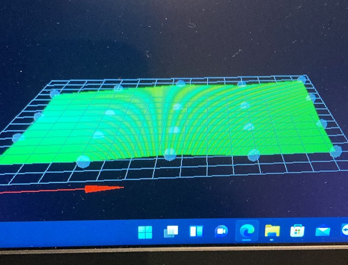
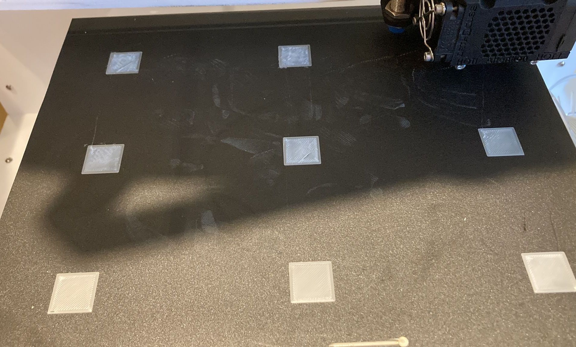
It should be a question of principle, how well does the height regulation work and what are the limits. We are often asked by customers where it is not working well and we are a bit at a loss. Here is an example of what is meant. The height map doesn't look that bad, but there are still some corrections although it shouldn't be that strong or vice versa.

The probe offset is set and has already been set to X0 Y0.
Both without big differences.In your experience, how exactly does it work and how can it be optimized if necessary?
Thank you in Advance

-
Well the image shows a 4 x 5 grid. That can mask all sorts of bed imperfections. I use a 20 x 20 grid to obtain the best correction possible.
Frederick
-
you're right, the topic was now much more general thought.
This was just one example of many. We've already done 30x30 meshes and then found out that the z movement weren't always correct. Therefore the question, what has which effect? what can be optimized in general?
Or can it be implemented better on the firmware side? -
@cr3d said in G29 Heightmap not working well:
We've already done 30x30 meshes
What hardware do you have that allows for a 30 x 30 grid?
and then found out that the rules weren't always correct.
What do you mean by "rules weren't always correct"?
Thanks.
Frederick
-
@fcwilt said in G29 Heightmap not working well:
What hardware do you have that allows for a 30 x 30 grid?
We tested this on our 600x500mm machines...
-
@cr3d said in G29 Heightmap not working well:
The probe offset is set and has already been set to X0 Y0.
What does this mean?
In general, the mesh compensation does work. In cases where it seems not to, the usual problems are misconfiguration, or mechanical problems. For mesh compensation to work correctly, the XY movement must not have any mechanical tilt or skew. the compensation assumes that the XY motion plane is perfect and compares that perfection to the probed result of the bed. The probe offsets must also be correct and not vary across the surface of the XY plane.
For a better evaluation we would need to see your relevant gcode.
-
@cr3d said in G29 Heightmap not working well:
@fcwilt said in G29 Heightmap not working well:
What hardware do you have that allows for a 30 x 30 grid?
We tested this on our 600x500mm machines...
This seems unlikely as the firmware is currently limited to 441 points or a 21x21 grid.
-
This could be relevant: https://habitoti.de/wordpress/bltouch-frustration/
-
The mesh is generated with a high-quality inductive sensor with high repeat accuracy.
the machines are extremely solid and no mechanical problem can be identified.I can't say exactly how many measuring points, but we found these "errors" with few as well as with many measuring points
What I would like to wish for is that the values that are compensated, i.e. the Z movement that is carried out, could be read out.
I meant with the probe offsets, that we use the correct probe offset from the nozzle but also a zero offset for testing..
-
One additional test, that can help determine probe offset changes is to run the probe out near a corner of the bed, use the probe to home Z in that location, then print a one layer test square there. If the probe z-offset is different in that location, then the locally zero'd test patch should look just as bad as when the bed was homed in the center. If, however, the test patch looks great, this means that the probe Z-offset has not changed between the center of the bed and the edge.