[3.4.0rc1] I think the bed heater is overheating?
-
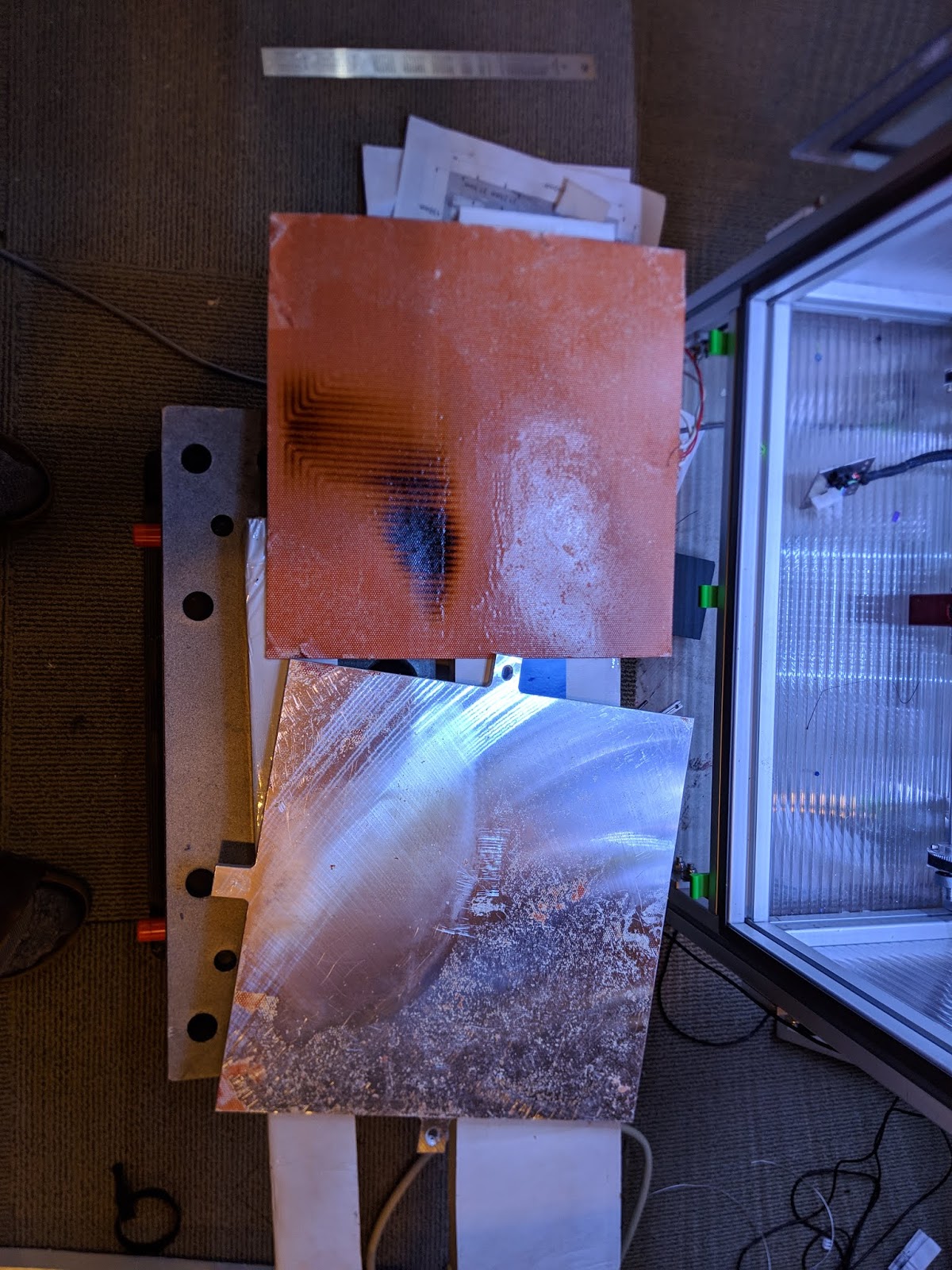
Started to heatsoak the V2.4 at 115 bed temp as usual and after a while it started smelling really really bad and couldn't figure out what it was until I looked at my extra corner bed thermistor which was at 116C.
That never happens, I can heat as long as I like at target 115C and it will go to max 113C.
Now, I don't know what has happened here as the printer hasn't printed anything after the upgrade to RC1.
I just wanted to document it here until I can test some more as I'm going to cool it down and downgrade to beta7 and see what happens.
I really hope I haven't burned the glue to the heater mat because it really stinks now.
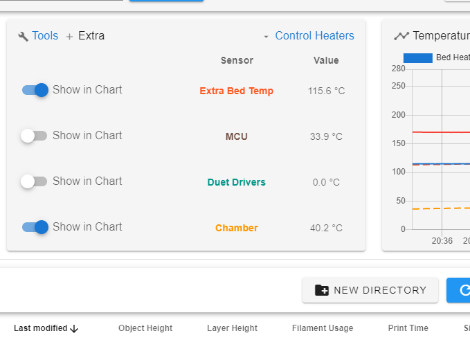
As you can see the extra corner bed thermistor shows higher temp than the actual mat thermistor.
; Configuration file for Duet 3 Mini 5+ (firmware version 3.3)
; executed by the firmware on start-up
;
; generated by RepRapFirmware Configuration Tool v3.3.2 on Mon Sep 13 2021 16:36:36 GMT+0200 (centraleuropeisk sommartid)
; Based on configuration by OC-Geek

; General preferences
M111 S0                	; Debugging off
G21                    	; Work in millimetres
G90                     ; send absolute coordinates...
M83                     ; ...but relative extruder moves

M669 K1                 ; select CoreXY mode

; Limit axis
M564 S1 H1             	; Forbid axis movements when not homed
; H1	Forbid movement of axes that have not been homed
; S1	Limit movement within axis boundaries

; Wait a moment for the CAN expansion boards to start
G4 S2

; ==================================
; Fysetc 12864 display Color
; ==================================

M918 P2 R6 C30 E4 F200000  	; Configure direct-connect display
; P2  	128x64 display using ST7567 display driver chip
; R6  	Display resistor ratio, in range 1 to 7. Only used with ST7567-based displays.
;		The default value of 6 is suitable for the Fysetc Mini 12864 display.
; C30	Display contrast, in range 0 to 100
; E4	The number of pulses generated by the rotary encoder per detent. Typical values are 2 and 4
; F...	SPI clock frequency in Hz, default 2000000 (i.e. 2MHz)

M150 X2 R0 U255 B0 P200 S3   ; Set LED colours
; X2 		LED type: X0 (default) = DotStar, X1 = NeoPixel, X2 = Panel 12864
; R,U,B		Set the LED colour (note Fystec uses GRB space instead ... (Red and Green switched over)
; S3 		Number of individual LEDs to set to these colours

; ==================================
; NETWORK
; ==================================

; Need to set up WIFI
; M587 S"SSID" P"PWD"
; This needs to be as a first step via USB like when fw ver is checked
; It is permanently stored in the card after that
; https://duet3d.dozuki.com/Guide/1.)+Getting+Connected+to+your+Duet

; Network
M550 P"voron2"          ; set printer name
M552 S1                                          ; enable network
M586 P0 S1                                       ; enable HTTP (for DWC)
M586 P1 S1                                       ; enable FTP (for remote backups)
M586 P2 S1                                       ; disable Telnet

; ==================================
; DRIVERS
; ==================================

; --- Z Drive map ---
;    B_______A
;    | 1 | 2 |
;    | ----- |
;    | 0 | 3 |
;     -------
;      front
;
; (looking at the printer from the top)

; Driver directions
; M569: Set motor driver direction, enable polarity and step pulse timing
; This command has LOT of parameters ... e.g. stealthChop2 ...
; Pnnn 		Motor driver number
; Snnn		Direction of movement 0 = backwards, 1 = forwards (default 1)

M569 P121.0 S1                                   ; E - physical drive 121.0 goes forwards

M569 P0.0 S1 D2                                  ; A -> Y - physical drive 0.0 goes forwards
M569 P0.1 S1 D2                                  ; B -> X - physical drive 0.1 goes forwards

M569 P0.3 S1                                     ; Z0 - physical drive 0.3 goes forwards
M569 P0.4 S0                                     ; Z1 - physical drive 0.4 goes backwards
M569 P0.5 S1                                     ; Z2 - physical drive 0.5 goes forwards
M569 P0.6 S0                                     ; Z3 - physical drive 0.6 goes backwards

M584 X0.0 Y0.1 Z0.3:0.4:0.5:0.6 E121.0           ; set drive mapping
M350 X16 Y16 Z16 E16 I1                          ; configure microstepping with interpolation
M92 X80.00 Y80.00 Z400.00 E400.00                ; set steps per mm

; Accelerations and speed are set in separate macro
M98 P"/macros/set_normal_speed.g"

; Stepper driver currents
; set motor currents (mA) and motor idle factor in per cent
; Drive currents
M906 X1400 Y1400 Z1200 E500 I70 ; XYZ and E current
M84 S120                        ; Idle timeout

; ==================================
; Endstops
; ==================================

; Xn,Yn endstop: 0 = none, 1 = low end, 2 = high end
; Snnn 	1 = switch-type (eg microswitch) endstop input
;		2 = Z probe (when used to home an axis other than Z)
;		3 = single motor load detection
;		4 = multiple motor load detection (see Notes)
; P"pin_name"

; Endstops
M574 X2 S1 P"121.io0.in"                       ; configure active-high endstop for high end on X via pin 121.io0.in
M574 Y2 S1 P"0.io1.in"                         ; configure active-high endstop for high end on Y via pin io1.in
M574 Z0 p"nil"                                  ; No Z endstop
                                                ; Extruder never stops :-)

; Axis travel limits                            ; Mind this is travel NOT print area
M208 X-4:300 Y0:305 Z-5:265                       ; Set axis minima - negative X is to have 0,0 on bed corner
                                                ; WARNING on Z not to hit the roof - this is set here

; Belt Locations
M671 X-65:-65:365:365 Y0:395:395:0 S20      ; Define Z belts locations (Front_Left, Back_Left, Back_Right, Front_Right)
											; Position of the bed leadscrews.. 4 Coordinates
											; Snn Maximum correction to apply to each leadscrew in mm (optional, default 1.0)
                                            ; S20 - 20 mm spacing
M557 X30:270 Y30:270 P7                     ; Define bed mesh grid (inductive probe, positions include the Y offset!)

; ==================================
; Bed heater
; ==================================
M308 S0 A"Bed Heater" P"temp0" Y"thermistor" T100000 B3950     ; configure sensor 0 as thermistor on pin temp0
;M308 S0 P"temp1" Y"thermistor" T100000 B3950     ; configure sensor 0 as thermistor on pin temp1
M950 H0 C"out0" Q10 T0                               ; create bed heater output on out0 and map it to sensor 0
M307 H0 R0.620 K0.495:0.000 D0.91 E1.35 S1.00 B0
;M307 H0 B0 R0.637 C222.4 D0.95 S1.00 V24.0
;M307 H0 B0 R0.602 C315.3 D0.89 S1.00 V24.0
;M307 H0 B1 S1.00                                ; Enable bang-bang mode for the bed heater and set PWM limit
M140 H0                                          ; map heated bed to heater 0
M143 H0 S120                                     ; set temperature limit for heater 0 to 120C

M308 S2 A"Extra Bed Temp" P"temp1" Y"thermistor" T100000 B3950     ; configure sensor 2 as thermistor on pin temp0
M143 H2 S130

; ==================================
; Hotend heater
; ==================================
;M308 S1 P"121.temp0" Y"thermistor" T100000 B4267 ; configure sensor 1 as thermistor on pin 121.temp0
M308 S1 P"121.temp0" Y"pt1000"                   ; configure sensor 1 as pt1000 on pin 121.temp0
M950 H1 C"121.out0" T1                           ; create nozzle heater output on 121.out0 and map it to sensor 1
M307 H1 R2.605 K0.363:0.000 D7.04 E1.35 S1.00 B0 V24.2
;M307 H1 B0 R2.638 C196.3 D6.34 S1.00 V24.2       ; NF Coated Copper nozzle 0.4
;M307 H1 B0 R2.406 C188.5 D6.38 S1.00 V24.2       ; HF CHT Nozzle 0.6
;M307 H1 R2.796 K0.530:0.000 D6.11 E1.35 S1.00 B0 V23.9
;M307 H1 R2.897 K0.551:0.000 D6.38 E1.35 S1.00 B0 V23.9
;M307 H1 B0 R2.518 C174.0 D6.14 S1.00 V23.8
;M307 H1 B0 R3.409 C154.0 D3.92 S1.00 V23.8
;M307 H1 B0 S1.00                                 ; disable bang-bang mode for heater  and set PWM limit
M143 H1 S280                                     ; set temperature limit for heater 1 to 280C

; ==================================
; SENSORS MISC
; ==================================

; Define MCU sensors which will be available in DWC Extra View
M308 S3 A"MCU" Y"mcu-temp" 				; Officially NOT supported on Mini 3 5+ however seem to work
M308 S4 A"Duet Drivers" Y"drivers" 		; This is not really working as it is just a threshold crossing

; ==================================
; CHAMBER SENSOR
; ==================================
M308 S10 A"Chamber" P"0.temp2" Y"thermistor" T100000 B3950

; ==================================
; Z PROBES K0 (Klicky mag probe) and K1 (Microswitch Z0)
; ==================================

; M558: Set Z probe type
	; P5/P8 	select a switch by default (normally closed) for bed probing between the In and Gnd pins of the Z-probe connector
	; C			specifies the input pin and the optional modulation pin. This parameter is mandatory
	; Tnnn 		Travel speed to and between probe points (mm/min)
	; Fnnn 		Feed rate (i.e. probing speed, mm/min) e.g. 60 is one mm per second
	; Hnnn 		Dive height (mm)
	; Annn 		Maximum number of times to probe each point, default 1
	; Snnn 		Tolerance when probing multiple times, default 0.03mm
	; Rnnn 		Z probe recovery time before the probing move is started , default zero (seconds)
	; B0		B1 Turn off all heaters while probing, default (B0) leaves heaters on.
	; I0		Invert (I1) or do not invert (I0, default) the Z probe reading

; G31: Set Current Probe status
	; K0		Z Probe Number
	; Pnnn 		Trigger value
	; Xnn Ynn 	Probe offset (from Noozle)
	; Znnn 		Trigger Z height - Set the said Z when the probe triggers !!

; MAG PROBE (GND, IO)
; -----------
; This is the Euclid probe with microswitch
M558 K0 P8 C"121.io2.in" T18000 F180 H10 A10 S0.0025
G31 K0 P500 X0 Y23.5 Z9 ;Z7.438

; Z-SWITCH
; -----------
; This is the microswitch which is pressed by the Noozle
M558 K1 P8 C"io5.in" T18000 F180 H3 A10 S0.0025 R0
; Omron micro switch
G31 K1 P500 X0 Y0 Z1.20

; ==================================
; Part cooling fan
; ==================================
M950 F0 C"121.out1"                              ; create fan 0 on pin 121.out1 and set its frequency
M106 P0 S0 H-1                                   ; set fan 0 value. Thermostatic control is turned off

; ==================================
; Hotend fan
; ==================================
M950 F1 C"121.out2"                              ; create fan 1 on pin 121.out2 and set its frequency
M106 P1 S1 H1 T45                                ; set fan 1 value. Thermostatic control is turned on

; ==================================
; MCU fan
; ==================================
M950 F2 C"!0.out4+0.out4.tach" Q25000              ; create fan 2 on pin out4 and set its frequency
M106 P2 H3:4 L0.2 X1.0 T30:50 C"Controller fan 1"  ; controlled by Sensor 3 - MCU
;M106 P2 H-1 C"Controller fan 1"

; ==================================
; Controller bay fan
; ==================================
M950 F3 C"!0.out3+0.out3.tach" Q25000              ; create fan 3 on pin out3 and set its frequency
M106 P3 H0 L0.2 X0.7 T60:120 C"Controller fan 2"
;M106 P3 H-1 C"Controller fan 2"

; ==================================
; Nevermore Filter fans
; ==================================
M950 F4 C"0.out5"                                ; create fan 4 on pin 0.out5 and set its frequency
M106 P4 H0 S0.65 T65 C"Nevermore fan"            ; set fan 4 value. Thermostatic control is turned on

; Tools
M563 P0 D0 H1                                    ; define tool 0
G10 P0 X0 Y0 Z0                                  ; set tool 0 axis offsets
G10 P0 R0 S0                                     ; set initial tool 0 active and standby temperatures to 0C

M955 P121.0 I05

; Input shaper
;M593 P"mzv" F47
;M593 P"zvdd" F70 S0.1
M593 P"mzv" F44

; Pressure advance
M572 D0 S0.055

; Custom settings are not defined

; defines global variables
M98 P"/macros/define_global_vars.g"

; Load override parameters
M501

T0
2022-02-15 20:59:10 m122 === Diagnostics === RepRapFirmware for Duet 3 Mini 5+ version 3.4.0rc1 (2022-02-09 10:27:22) running on Duet 3 Mini5plus WiFi (standalone mode) Board ID: H1668-Y296U-D65J0-40KMA-KR03Z-RK6ZH Used output buffers: 3 of 40 (31 max) === RTOS === Static ram: 103652 Dynamic ram: 116952 of which 12 recycled Never used RAM 17976, free system stack 152 words Tasks: NETWORK(ready,14.5%,206) HEAT(notifyWait,0.0%,315) Move(notifyWait,0.0%,268) CanReceiv(notifyWait,0.0%,772) CanSender(notifyWait,0.0%,356) CanClock(delaying,0.0%,337) TMC(notifyWait,1.2%,71) MAIN(running,83.4%,428) IDLE(ready,0.0%,29) AIN(delaying,0.8%,264), total 100.0% Owned mutexes: WiFi(NETWORK) === Platform === Last reset 00:41:31 ago, cause: power up Last software reset at 2022-02-14 21:22, reason: User, GCodes spinning, available RAM 18104, slot 2 Software reset code 0x0003 HFSR 0x00000000 CFSR 0x00000000 ICSR 0x00000000 BFAR 0xe000ed38 SP 0x00000000 Task MAIN Freestk 0 n/a Error status: 0x00 MCU revision 3, ADC conversions started 2491216, completed 2491215, timed out 0, errs 0 Step timer max interval 935 MCU temperature: min 33.9, current 34.2, max 34.2 Supply voltage: min 24.3, current 24.4, max 24.4, under voltage events: 0, over voltage events: 0, power good: yes Heap OK, handles allocated/used 99/5, heap memory allocated/used/recyclable 2048/232/162, gc cycles 0 Events: 1 queued, 1 completed Driver 0: pos 12800, standstill, SG min 0, read errors 0, write errors 0, ifcnt 19, reads 51320, writes 0, timeouts 0, DMA errors 0, CC errors 0 Driver 1: pos 11200, standstill, SG min 2, read errors 0, write errors 0, ifcnt 19, reads 51320, writes 0, timeouts 0, DMA errors 0, CC errors 0 Driver 2: pos 24000, standstill, SG min 0, read errors 0, write errors 0, ifcnt 9, reads 51320, writes 0, timeouts 0, DMA errors 0, CC errors 0 Driver 3: pos 0, standstill, SG min 2, read errors 0, write errors 0, ifcnt 16, reads 51320, writes 0, timeouts 0, DMA errors 0, CC errors 0 Driver 4: pos 0, standstill, SG min 2, read errors 0, write errors 0, ifcnt 16, reads 51320, writes 0, timeouts 0, DMA errors 0, CC errors 0 Driver 5: pos 0, standstill, SG min 2, read errors 0, write errors 0, ifcnt 16, reads 51320, writes 0, timeouts 0, DMA errors 0, CC errors 0 Driver 6: pos 0, standstill, SG min 2, read errors 0, write errors 0, ifcnt 16, reads 51320, writes 0, timeouts 0, DMA errors 0, CC errors 0 Date/time: 2022-02-15 20:59:08 Cache data hit count 4294967295 Slowest loop: 4.75ms; fastest: 0.13ms === Storage === Free file entries: 10 SD card 0 detected, interface speed: 22.5MBytes/sec SD card longest read time 3.3ms, write time 0.0ms, max retries 0 === Move === DMs created 83, segments created 11, maxWait 0ms, bed compensation in use: none, comp offset 0.000 === MainDDARing === Scheduled moves 27, completed 27, hiccups 0, stepErrors 0, LaErrors 0, Underruns [0, 0, 0], CDDA state -1 === AuxDDARing === Scheduled moves 0, completed 0, hiccups 0, stepErrors 0, LaErrors 0, Underruns [0, 0, 0], CDDA state -1 === Heat === Bed heaters 0 -1 -1 -1, chamber heaters -1 -1 -1 -1, ordering errs 0 Heater 0 is on, I-accum = 0.4 Heater 1 is on, I-accum = 0.0 === GCodes === Segments left: 0 Movement lock held by null HTTP is idle in state(s) 0 Telnet is idle in state(s) 0 File is idle in state(s) 0 USB is idle in state(s) 0 Aux is idle in state(s) 0 Trigger is idle in state(s) 0 Queue is idle in state(s) 0 LCD is idle in state(s) 0 SBC is idle in state(s) 0 Daemon is idle in state(s) 0 Aux2 is idle in state(s) 0 Autopause is idle in state(s) 0 Code queue is empty === CAN === Messages queued 5081, received 11290, lost 0, boc 0 Longest wait 0ms for reply type 0, peak Tx sync delay 264, free buffers 18 (min 18), ts 2823/2823/0 Tx timeouts 0,0,0,0,0,0 === Network === Slowest loop: 202.75ms; fastest: 0.06ms Responder states: HTTP(0) HTTP(0) HTTP(0) HTTP(0) FTP(0) Telnet(0), 0 sessions HTTP sessions: 1 of 8 - WiFi - Network state is active WiFi module is connected to access point Failed messages: pending 0, notready 0, noresp 1 WiFi firmware version 1.26 WiFi MAC address f0:08:d1:02:eb:c9 WiFi Vcc 3.36, reset reason Power up WiFi flash size 2097152, free heap 24272 WiFi IP address 192.168.1.191 WiFi signal strength -56dBm, mode 802.11n, reconnections 0, sleep mode modem Clock register 00002002 Socket states: 0 0 0 0 0 0 0 0 -
Actually the PEI sheet just loosened completely from the spring steel sheet.
-
Did the main bed thermistor lose contact?
-
@phaedrux I'll have a look as soon as it cools down enough to touch. I'll take the bed off and see.
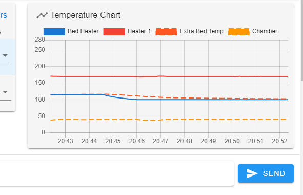
The graph looks fine otherwise though.
-
Was the bed heater attached by 3M adhesive sheet or with RTV silicone?
The 3M adhesive isn't a good option for high temps and will delaminate eventually.
-
@phaedrux It's some higher speced 3M adhesive as recommended from Fermio Labs
The mat and thermistor feels fine though, firm and set.
I'm going to remount the bed and do some tests. Glad I had the extra thermistor.
The PEI just rolled off.
-
Maybe so, but I'd still be more inclined to follow Keenovo's own recommendations.
edcf5a62-3a6a-41fb-8b45-2e4803a65975-User's-Manual-Keenovo-Flexible-Heaters.pdf User's-Manual-Keenovo-Flexible-Heaters.pdf
-
@phaedrux Yes, I have no knowledge of that myself so I have installed as Fermio has recommended it. When asked they say that the Keenovo recommendation is for general purpose usage in wet areas for heater tanks and other places not as pristine as inside a printer.
There will be a few thousand Vorons failing soon if the 3M adhesive doesn't hold up. Usually the RTV is only placed around the edges as a precaution. It will not stop the mat from loosen from the aluminium bed and cause thermistor misreadings if the adhesive fails.
Anyhow, that's a different discussion.
However, without knowing of even having thought much about it, I think that if the thermistor and mat would have losened from the bed it would've read a higher value than the actual bed as the energy cannot be absorbed by the metal and the thermistor is attached on top of the mat. Now, it read a lower value.
-
Well, Haven't been able to recreate anything suspicious at all.
What happened was strange, as the overwhelming smell of overheating glue and the self peeling PEI plus the extra bed end thermistor reading a value much to high. Never measured more than the set temperature before. Always 5 - 10C lower.
Anyway, as I can't recreat this it's probably for the best to close this thread.
-
@phaedrux said in [3.4.0rc1] I think the bed heater is overheating?:
Maybe so, but I'd still be more inclined to follow Keenovo's own recommendations.
Is the high temp RTV method preferred over that 3M double sided sheet? I have 3M as the main adhesive and RTV around, heating the bed up to 110C nominal.
-
@zapta said in [3.4.0rc1] I think the bed heater is overheating?:
@phaedrux said in [3.4.0rc1] I think the bed heater is overheating?:
Maybe so, but I'd still be more inclined to follow Keenovo's own recommendations.
Is the high temp RTV method preferred over that 3M double sided sheet? I have 3M as the main adhesive and RTV around, heating the bed up to 110C nominal.
It would be preferred for me. From the specs I've been able to find of the 3M sheet it's not really meant for long term high heat use or repeated heat cycling. Eventually it deteriorates. Adding RTV to the edges to seal them at least keeps them from peeling away, and perhaps through suction would keep the center from releasing.
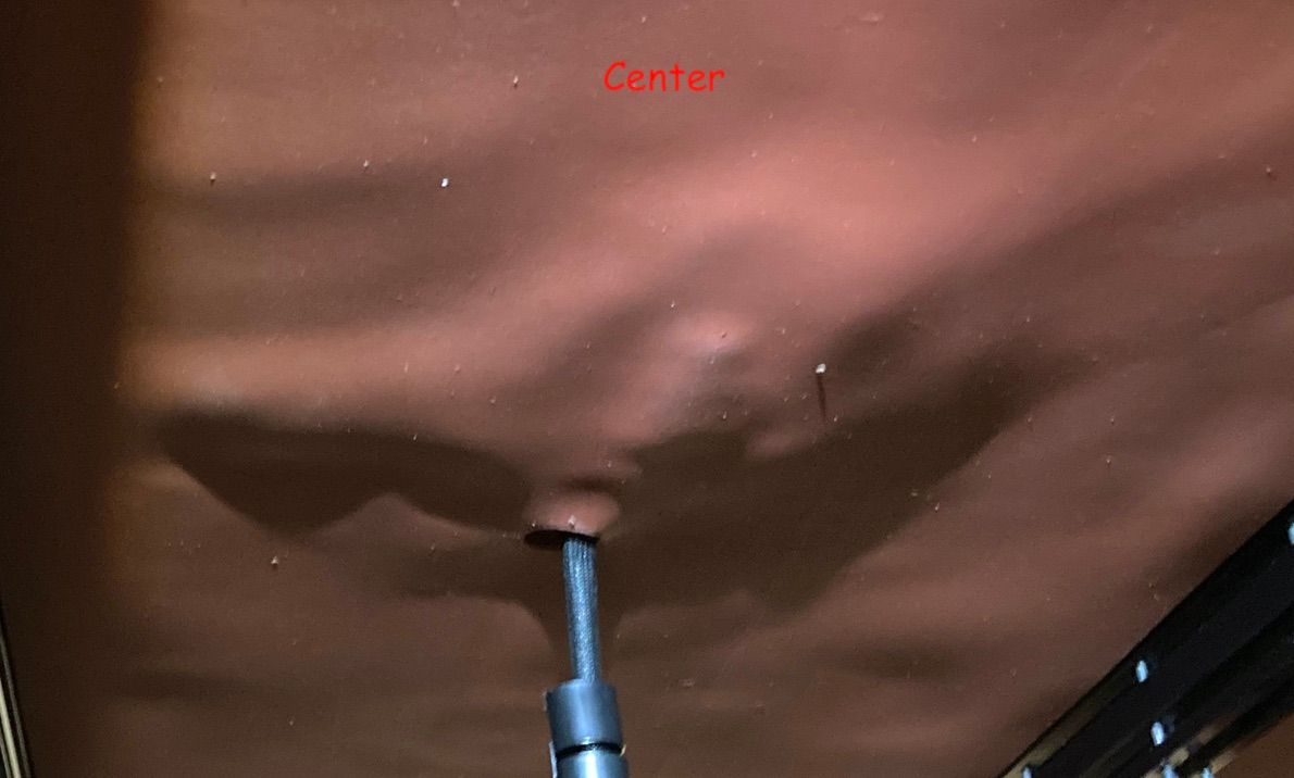
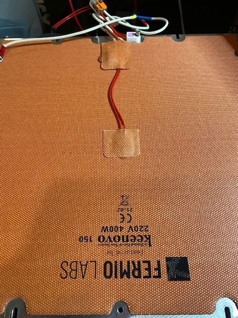
Here the 3M has given way at the center of the mat. It's not a good design as there is no strain relief on the cabling and at temp the 3M has let go from the gentle pull of the cable.
There have been other cases where pockets have formed and the heater has burnt up from lack of contact causing hot spots.
Given the low cost of 500c RTV silicone ($10) why not?
-
@phaedrux said in [3.4.0rc1] I think the bed heater is overheating?:
Given the low cost of 500c RTV silicone ($10) why not?
Yes, it's sounds as the right thing to do. In my case I already have a bed with the 3M adhesive and RTV around the edges as you recommended in an old thread. Will add it to my TODO list. Not sure how easy it is to clean the existing RTV from the bed.
The reason I am looking into is is a thermal fuse blowout I had a few days ago. It's a 115C fuse with a bed I heat to 110C (originally I planned going only up to 100C). Everything looks good and I ordered a 135C thermal fuse but may go the full RTV route down the road.
-
@phaedrux Yes, you are of course right. More safety is never wrong. In my case I bought the variant which goes right to the edge and only leaves < 5mm either side.
If you want to go full RTV one have to either remove the 3M glue from the heater or buy the version without 3M tape.
I have this idea of making a thinish clamp in aluminium. Sort of a skeleton frame which is hold to place by small spring loaded screws in the extra three holes which the Voron beds usually have to be compatible with the 1.8/Trident models. It wouldn't have any other purpose than give some peace of mind and maybe a stress relief for the heater/thermistor cables.
Well, we'll see. It's not stupid expensive to send out for laser cutting.
-
@zapta said in [3.4.0rc1] I think the bed heater is overheating?:
Not sure how easy it is to clean the existing RTV from the bed.
Not easy. The 3M tape can be dissolved with a citrus oil solvent, but the RTV silicone would need to be cut away with a blade. Not likely worth the effort.
-
@phaedrux said in [3.4.0rc1] I think the bed heater is overheating?:
Not likely worth the effort.
I got a nice 250mm bed from a european vendors that doesn't ship anymore to the US. Will need to find another source.
")
-
@zapta Is it possible to attach a bed with only RTV? Why is this not the norm? The 3M adhesive kinda sucks for anything over 110 C. Does Keenovo deliver pads with no adhesive?
Homegrown, grass fed and organically built 350mm delta
-
@Velvia said in [3.4.0rc1] I think the bed heater is overheating?:
Does Keenovo deliver pads with no adhesive?
You can custom order from them.
-
@Velvia, I read that this is the recommended way now, but I don't have any experience with it, my heater is attached with that 3M high temp adhesive. I just added RTF along the edges.
-
The bed plate acts as a heat sink/heat spreader for the heater. If part of the heater separates from the bed, that part gets extra hot. Here's what happens to the heater when the 3M adhesive starts to let go: