Min and max axis end-stop connections
-
Hi, I'm back after a while to ask a clarification about endstops and related connections.
On the Duet 2 wifi, each endstop connector has 3 contacts (+3.3v, signal and gnd + shielding).
So 3 endstops = 3 cables of (3+1) wires = 9 + 1 pinI would like to know if this is essential or if the gnd and +3.3v can be merged.
The problem is that I use an external totem pole for electronics and need to sort out the huge amount of cables and connectors that I am currently using to connect everything to the printer. And I wanted to reduce, if possible, the number of connectors.
Wanting to install endstops for both min and max of each axis, and having 4 independent Z motors, in addition to the 2 sensors for the filament, I would get in total: 14 3+1 pin cables. (that is 42 wires and 14 shields)
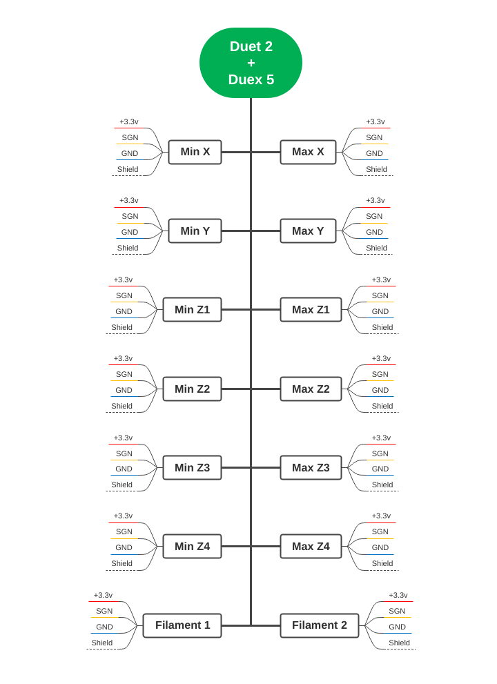
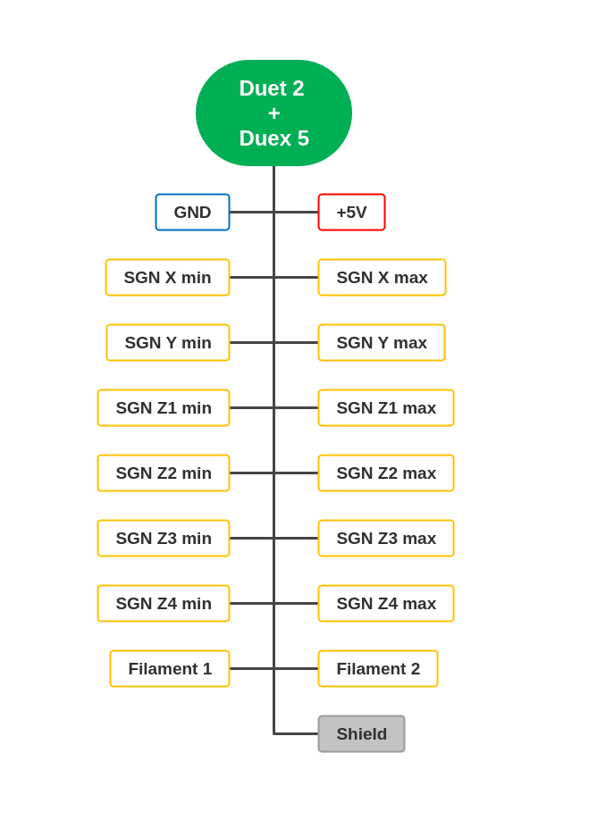
To reduce the number of connectors and especially wires, I wanted to know if I could use 14 signal + 3.3v + gnd + shield pins, for a total of just 16+1 pins.
Thanks
Bernardo -
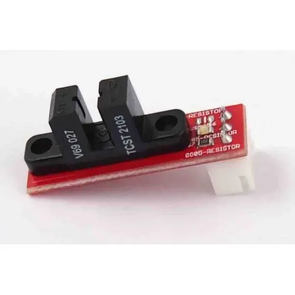
@bernardomattiucci what type of endstops are you planning to use?
Owns various duet boards and is the main wiki maintainer for the Teamgloomy LPC/STM32 port of RRF. Assume I'm running whatever the latest beta/stable build is
-
@bernardomattiucci You can only have one endstop per motor in RRF. Either min or max, not both. M208 sets the axis length, and a soft limit once the axis has homed.
You can have two endstops, but only one will be used for homing. The second can be used as a trigger for the axis moving too far. However, if your axis is moving beyond the limits set by M208, you've got other problems.
Ian
Bed-slinger - Mini5+ WiFi/1LC | RRP Fisher v1 - D2 WiFi | Polargraph - D2 WiFi | TronXY X5S - 6HC/Roto | CNC router - 6HC | Tractus3D T1250 - D2 Eth
-
@jay_s_uk optical, similar to this
-
not a problem.
I only need to provide both endstops because the printer can be mounted in different ways and only after the assembly you can decide which endstop to assign to the minimum limit -
@bernardomattiucci I'd think sharing 5V and GND shouldn't be a problem, but check the current draw of 12x optical sensors (plus the filament sensors) is not higher than the connector specification (3A for KK, I think), or the limits of the 5V regulator. See https://docs.duet3d.com/Duet3D_hardware/Duet_2_family/Duet_2_WiFi_Ethernet_Hardware_Overview#operating-limits and https://docs.duet3d.com/Duet3D_hardware/Duet_2_family/DueX2_and_DueX5#operating-limits
Duet 2 5V current limit - 2.0A total on 5V and 3.3v, including the internal current consumption (around 200-300mA), any PanelDue or other display, and any endstops/Z probes that draw significant power.
DueX 5V current limit - (supplied by connected Duet 2) 1A total on PWM pins and fans (when internal 5V is selected)Or use external 5V power supply on DueX.
Ian