Duet3D Logo Duet3D
    • Tags
    • Documentation
    • Order
    • Register
    • Login

    I could use some help

    Scheduled Pinned Locked Moved
    Duet Hardware and wiring
    11
    682
    63.5k
    Loading More Posts
    • Oldest to Newest
    • Newest to Oldest
    • Most Votes
    Reply
    • Reply as topic
    Log in to reply
    This topic has been deleted. Only users with topic management privileges can see it.
    • A Former User?
      A Former User @fcwilt
      last edited by

      @fcwilt installation? You mean I have to install them?????

      A Former User? 1 Reply Last reply Reply Quote 1
      • A Former User?
        A Former User @A Former User
        last edited by

        @droftarts as Ian might say, and then he’d send a link to the documentation.

        A Former User? 1 Reply Last reply Reply Quote 0
        • A Former User?
          A Former User @A Former User
          last edited by

          @fcwilt but I have read them.

          A Former User? 1 Reply Last reply Reply Quote 0
          • A Former User?
            A Former User @A Former User
            last edited by

            @fcwilt @droftarts

            Just thought I’d share this with you:

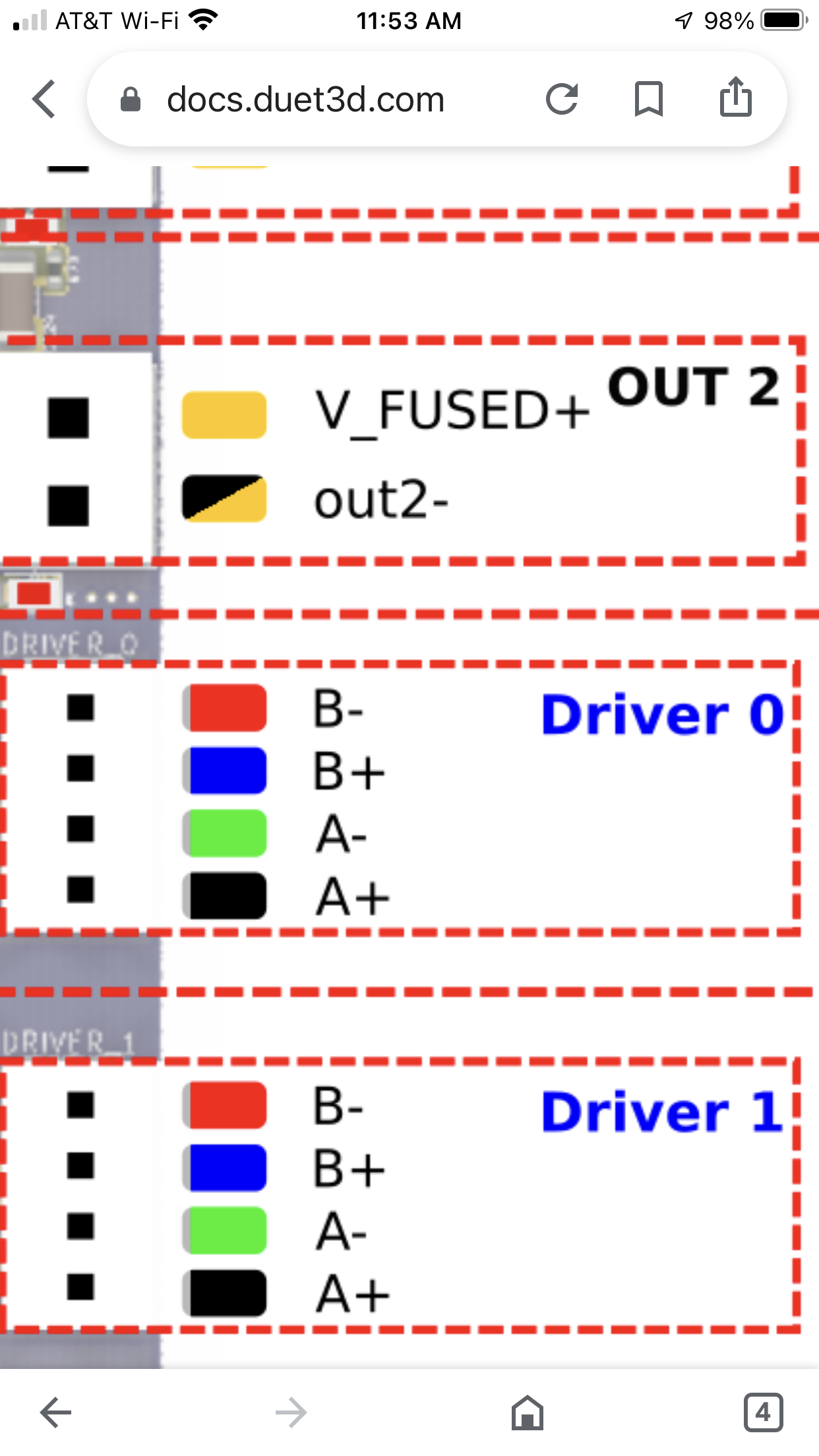
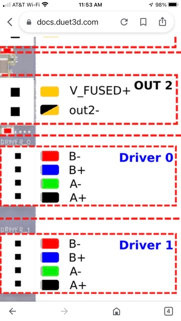
            This is how the board of the Duet3D Mini 5+ is set up:

            F4E73741-43E1-4167-B192-3A647557E930.png

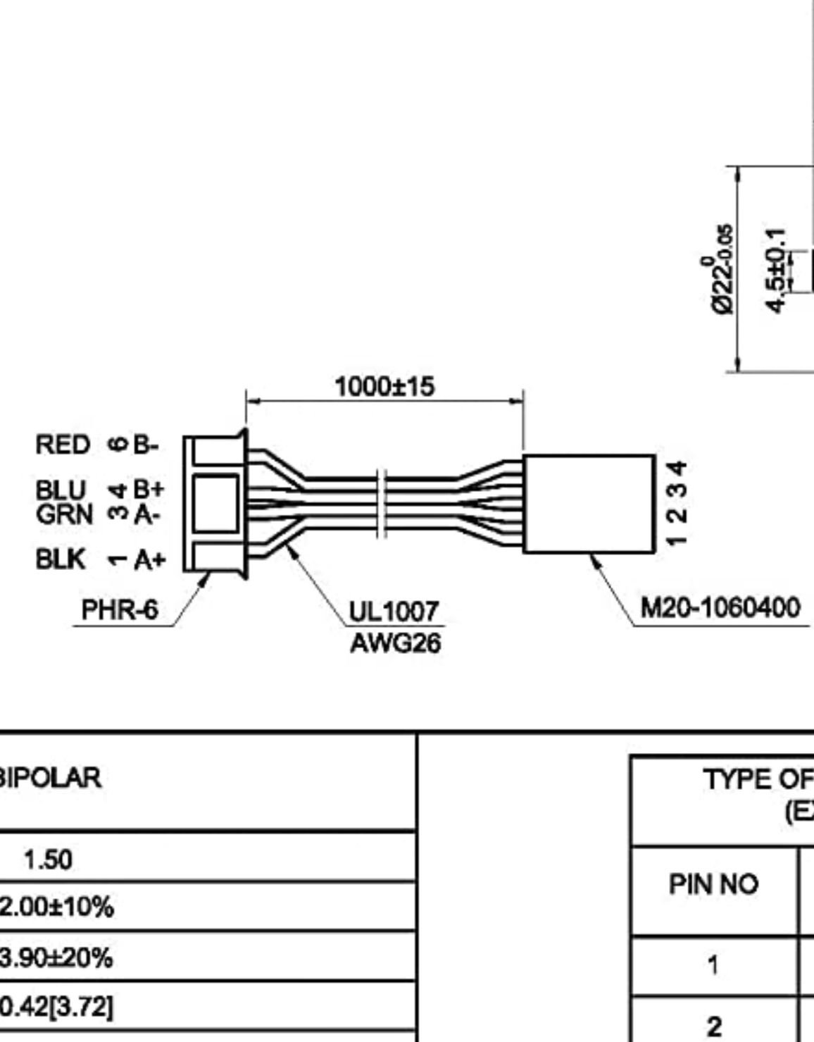
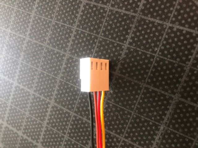
            And this is how the motors I hope to install today are set up:

            FC26C606-E6B7-47B1-99D8-8097B3EC5A33.jpeg

            Talk about harmonious!

            Mac

            A Former User? 1 Reply Last reply Reply Quote 1
            • A Former User?
              A Former User @A Former User
              last edited by

              @droftarts @fcwilt

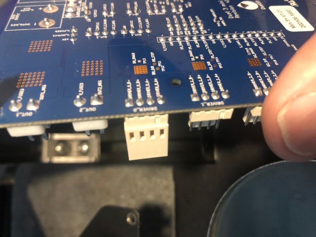
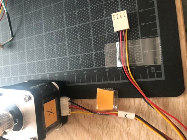
              Here’s a series a pictures I’d like to share with you. They tell a story. I hope you’ll figure it out.

              0A6CD37A-9F43-4502-871D-74DD7845AC90.jpeg 30E4A125-7B32-4907-BEAC-A4C188E1FF84.jpeg A8926053-72FB-4000-B109-1AD5855E631A.png F99A5766-A0E6-4051-91B2-A5BB2862C29F.jpeg

              A Former User? 1 Reply Last reply Reply Quote 0
              • A Former User?
                A Former User @A Former User
                last edited by

                @fcwilt @droftarts Do you see what I did wrong? With all 4 motors?

                Mac

                fcwiltundefined 1 Reply Last reply Reply Quote 0
                • fcwiltundefined
                  fcwilt @A Former User
                  last edited by

                  @mac said in I could use some help:

                  @fcwilt @droftarts Do you see what I did wrong? With all 4 motors?

                  Mac

                  No I don't.

                  Based on the diagram you posted the yellow/brown pair are connecting to one phase of the stepper and the red/black pair are connecting to the other phase.

                  And the connections to the Duet seem correct.

                  What do you think is wrong?

                  Frederick

                  Printers: a small Utilmaker style, a small CoreXY and a E3D MS/TC setup. Various hotends. Using Duet 3 hardware running 3.4.6

                  A Former User? 1 Reply Last reply Reply Quote 0
                  • A Former User?
                    A Former User @fcwilt
                    last edited by A Former User

                    @fcwilt this is why I’m not an electrical engineer. I decided to try shorting the two phases to make sure my “discovery” was correct. As you have indicated, post’s 1 and 3 (bottom and 3rd up) are a phase, and post’s 2 and 4 are the other phase. So that means red and yellow go together, and brown and black go together. Whew, my head is spinning!

                    Thanks for commenting. Your affirmation is helping, a lot.

                    Mac

                    fcwiltundefined 1 Reply Last reply Reply Quote 0
                    • fcwiltundefined
                      fcwilt @A Former User
                      last edited by

                      @mac said in I could use some help:

                      @fcwilt this is why I’m not an electrical engineer. I decided to try shorting the two phases to make sure my “discovery” was correct. As you have indicated, post’s 1 and 3 (bottom and 3rd up) are a phase, and post’s 2 and 4 are the other phase. So that means red and yellow go together, and brown and black go together. Whew, my head is spinning!

                      Thanks for commenting. Your affirmation is helping, a lot.

                      Mac

                      On the Stepper and the Duet A+ and A- are one phase, B+ and B- are the other phase.

                      Frederick

                      Printers: a small Utilmaker style, a small CoreXY and a E3D MS/TC setup. Various hotends. Using Duet 3 hardware running 3.4.6

                      A Former User? 1 Reply Last reply Reply Quote 0
                      • A Former User?
                        A Former User @fcwilt
                        last edited by

                        @fcwilt it’s hard for me to understand this because what I always see is A+, A-, B+, B-. I don’t know which wire of each phase is minus, or plus for that matter. That’s what’s hanging me up on this issue. If it doesn’t water, (I’ve heard that), why is the wiring of the motors presented that way? Why does Duet3D label their pins that way? You know?

                        fcwiltundefined 1 Reply Last reply Reply Quote 0
                        • fcwiltundefined
                          fcwilt @A Former User
                          last edited by fcwilt

                          @mac said in I could use some help:

                          @fcwilt it’s hard for me to understand this because what I always see is A+, A-, B+, B-. I don’t know which wire of each phase is minus, or plus for that matter. That’s what’s hanging me up on this issue. If it doesn’t water, (I’ve heard that), why is the wiring of the motors presented that way? Why does Duet3D label their pins that way? You know?

                          Here is a fairly typical stepper diagram showing how applied signals translate into steps:

                          Stepper Chart.png

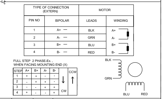
                          Down on the lower left, notice the chart that has STEP 1,2,3,4 in the left column.

                          Notice that for Step 1 the + and - symbols under the columns for A+, B+, A- and B-.

                          That tells you when you apply a positive voltage to A+ and B+ and the corresponding negative voltage to A- and B- the stepper will move to Step 1.

                          As the board changes the voltages applied to the coils, so they match the chart, the stepper will move from Step 1 to Step 2 to Step 3 to Step 4.

                          And while it may not be obvious if the polarity applied to one of the coils happens to be the opposite of what the chart calls for the only thing that happens is the stepper turns in the reverse direction.

                          So, as long as you connect the A terminals for the Duet to the one of the coils and the B terminals of the Duet to other coil you can control the direction of rotation with the S parameter of the M569 commands.

                          Frederick

                          Printers: a small Utilmaker style, a small CoreXY and a E3D MS/TC setup. Various hotends. Using Duet 3 hardware running 3.4.6

                          A Former User? 1 Reply Last reply Reply Quote 0
                          • A Former User?
                            A Former User @fcwilt
                            last edited by

                            @fcwilt it truly is a magic borne of human ingenuity.

                            The motors didn’t show up today. Bummer. I’m hope for mail on Sunday now.

                            So could you talk about 24volts versus 12 volts. I know the change would cost me, but what are the hardcore benefits?

                            Mac

                            deckingmanundefined 1 Reply Last reply Reply Quote 0
                            • deckingmanundefined
                              deckingman @A Former User
                              last edited by deckingman

                              @mac said in I could use some help:

                              @fcwilt it truly is a magic borne of human ingenuity.

                              The motors didn’t show up today. Bummer. I’m hope for mail on Sunday now.

                              So could you talk about 24volts versus 12 volts. I know the change would cost me, but what are the hardcore benefits?

                              Mac

                              I already addressed that question in my post of 30th June. Scroll up and read the last bit again. Essentially you could get more torque out of the motors and use more powerful heaters. But if 12V gives you enough torque and enough heater power for your printer, you'll not see any benefit.

                              Ian
                              https://somei3deas.wordpress.com/
                              https://www.youtube.com/@deckingman

                              A Former User? 1 Reply Last reply Reply Quote 0
                              • A Former User?
                                A Former User @deckingman
                                last edited by A Former User

                                @fcwilt the motors arrived at 8:55 PM.

                                528982D4-5225-4DDB-A55B-E22109A17650.png

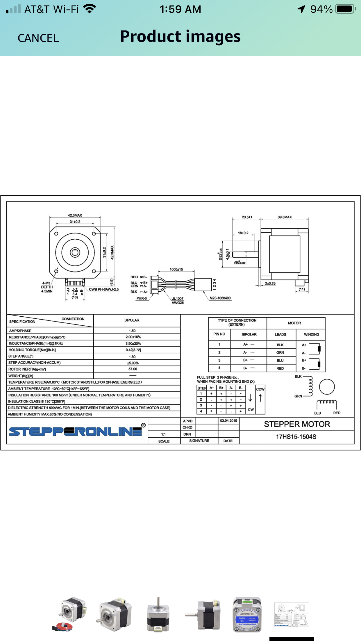
                                What, exactly, does RRF want to know about these motors?

                                What line of the config.g file needs to be edited, and how should it appear with the correct info?

                                Mac

                                deckingmanundefined 1 Reply Last reply Reply Quote 0
                                • deckingmanundefined
                                  deckingman @A Former User
                                  last edited by

                                  @mac Motor current is all. A good setting is about 85% of the rating. So around 1.2 to 1.3 amps (1200 to 1300 mA) for those motors which are rated at 1.5Amps.

                                  Ian
                                  https://somei3deas.wordpress.com/
                                  https://www.youtube.com/@deckingman

                                  A Former User? 1 Reply Last reply Reply Quote 0
                                  • A Former User?
                                    A Former User @deckingman
                                    last edited by

                                    @deckingman just finished installing them. It all went well.

                                    fcwiltundefined 1 Reply Last reply Reply Quote 1
                                    • fcwiltundefined
                                      fcwilt @A Former User
                                      last edited by

                                      @mac said in I could use some help:

                                      @deckingman just finished installing them. It all went well.

                                      Once you are ready to test the new steppers remember to:

                                      • execute M564 H0 S0 so you can jog each axis without homing or worrying about axis limits.
                                      • use the jog buttons to verify each axis is moving in the correct direction

                                      In the homing code I posted for you there was an absolute move at the end of each file.

                                      Comment those absolute moves out for now, until we know the homing moves are working.

                                      Frederick

                                      Printers: a small Utilmaker style, a small CoreXY and a E3D MS/TC setup. Various hotends. Using Duet 3 hardware running 3.4.6

                                      A Former User? 1 Reply Last reply Reply Quote 0
                                      • A Former User?
                                        A Former User @fcwilt
                                        last edited by

                                        @fcwilt my clock says 10:45; I've been up since 2 AM.

                                        I just plugged the power into the machine.

                                        My plan is to use RRF to tell the config.g file about these new motors. I'm still UNCLEAR as to what I should tell it. I'm also unclear about how to code it.

                                        You referred to some code you wrote? Recently, or before?

                                        I'm going to take this one step at a time, and try not to jump forwards without knowing where I'm going.

                                        Mac

                                        deckingmanundefined A Former User? 2 Replies Last reply Reply Quote 0
                                        • deckingmanundefined
                                          deckingman @A Former User
                                          last edited by

                                          @mac There is an old adage which goes something like, "catch a man a fish and he'll feed himself for a day, but teach a man how to catch fish and he'll feed himself for life". Now I'm not trying to be disrespectful in any way, and I'll continue to help when I can, but if we carry on like this, you will have an endless list of questions and especially with the time differences due to geographic locations, you are going to have to wait for the answers. That's only going to add to your frustrations.

                                          I'd like to teach you how to fish rather than keep feeing you now and then. So might I respectfully suggest, that you start looking at the documentation https://docs.duet3d.com/. Ian ( @droftarts ) has put a lot of time and effort into it and it really is very user friendly. Just start typing something in the search box at the top (e.g. "stepper motors") and it'll return a host a relevant topics which in turn will give you the information you need - often with actual code examples.

                                          If you get used to doing this, you'll find you get all the answers you need much more quickly. Of course, we fellow users are on the whole a friendly bunch and we'll continue to help as a when our commitments allow. But we only know what we know from reading the documentation (and asking the odd question now and again).

                                          Ian
                                          https://somei3deas.wordpress.com/
                                          https://www.youtube.com/@deckingman

                                          A Former User? 1 Reply Last reply Reply Quote 0
                                          • A Former User?
                                            A Former User @A Former User
                                            last edited by

                                            @mac Okay, I found the "code." (It was back at 510.)

                                            First, I feel like I have to tell my config.g that these new motors are X, where X is 1.2 - 1.3 amps / 1200 - 1300 mA.

                                            I just set all the the motors to 1200 mA.

                                            NOTE: I keep looking at the Z motor / Steps per mm; it's set at 4000? The Max. Speed Change (mm/s) is set at 1, the Max. Speed (mm/s) is set at 10, and the Acceleration (mm/s-squared) is set at 200? Is that right?

                                            fcwiltundefined 1 Reply Last reply Reply Quote 0
                                            • First post
                                              Last post
                                            Unless otherwise noted, all forum content is licensed under CC-BY-SA