• Tags
  • Documentation
  • Order
  • Register
  • Login
Duet3D Logo Duet3D
  • Tags
  • Documentation
  • Order
  • Register
  • Login

1XD Closed Loop Servo Setup

Scheduled Pinned Locked Moved
Duet Hardware and wiring
8
41
2.6k
Loading More Posts
  • Oldest to Newest
  • Newest to Oldest
  • Most Votes
Reply
  • Reply as topic
Log in to reply
This topic has been deleted. Only users with topic management privileges can see it.
  • undefined
    fcwilt @code7
    last edited by 1 Jul 2022, 22:11

    @code7

    What is it that you don't understand? Do the items below cover it?

    • You need to feed the board power on the VIN terminals.

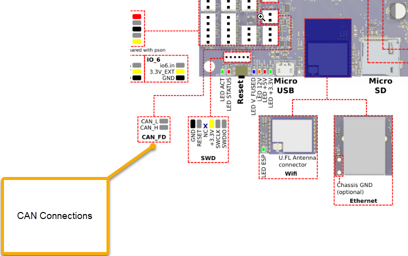
    • You need to connect one of the boards CAN jacks to the Duet 3 Mini but it does not have CAN jacks - just a 2 pin connector.

    Duet 3 Mini CAN Connections.png

    Printers: a small Utilmaker style, a small CoreXY and a E3D MS/TC setup. Various hotends. Using Duet 3 hardware running 3.4.6

    undefined 1 Reply Last reply 1 Jul 2022, 23:01 Reply Quote 1
    • undefined
      code7 @fcwilt
      last edited by 1 Jul 2022, 23:01

      @fcwilt Thanks. The picture and tips really help and the wiring the CAN-FD Bus makes sense now after revisiting the link.

      Could you give me an example of how the config.g would look with this scenario?

      Delta Printer Using a Duet 2 Wifi v1.04c, FW3.4.0beta2, Duet WiFi sever 1.26, Duet Web Control 3.3.0

      undefined undefined 2 Replies Last reply 2 Jul 2022, 01:03 Reply Quote 0
      • undefined
        alankilian @code7
        last edited by alankilian 7 Feb 2022, 01:06 2 Jul 2022, 01:03

        @code7

        THIS PAGE states which pins are PWM capable.

        Then just use the normal PWM syntax to configure a pin and set the value as shown HERE.

        SeemeCNC Rostock Max V3 converted to V3.2 with a Duet2 Ethernet Firmware 3.2 and SE300

        1 Reply Last reply Reply Quote 1
        • undefined
          fcwilt @code7
          last edited by 2 Jul 2022, 01:22

          @code7 said in 1XD Servo Setup:

          @fcwilt Thanks. The picture and tips really help and the wiring the CAN-FD Bus makes sense now after revisiting the link.

          Could you give me an example of how the config.g would look with this scenario?

          For the most part inputs, outputs, etc. are treated much like the same on the main board.

          What differs is the need for a board address

          ; 3HC temp sensors
          M308 S0 P"1.temp0" Y"pt1000" ; configure sensor (S), name (A), pin name (P), type (Y), properties (T,B)
          M308 S1 P"1.temp1" Y"thermistor" T100000 B4725 C7.06e-8 ; configure sensor (S), name (A), pin name (P), type (Y), properties (T,B)
          M308 S2 P"1.temp2" Y"pt1000" ; configure sensor (S), name (A), pin name (P), type (Y), properties (T,B)
          ; 6HC temp sensors
          M308 S3 P"temp1" Y"pt1000" ; configure sensor (S), name (A), pin name (P), type (Y), properties (T,B)
          M308 S4 P"temp0" Y"thermistor" T100000 B4267 ; configure sensor (S), name (A), pin name (P), type (Y), properties (T,B)

          Notice the temp sensor inputs on the 3HC board, which has an assigned address of 1.

          When specifying a temp sensor input on that board the P parameter needs both the address and the pin name - thus the P"1.temp0" above.

          Every board on the CAN bus has a unique address. How the address is set varies with the specific type of board. And every board type has a default address from the factory. IF that default address is all you need than you can use it.

          Frederick

          Printers: a small Utilmaker style, a small CoreXY and a E3D MS/TC setup. Various hotends. Using Duet 3 hardware running 3.4.6

          undefined 1 Reply Last reply 2 Jul 2022, 05:12 Reply Quote 0
          • undefined
            code7 @fcwilt
            last edited by code7 7 Feb 2022, 05:14 2 Jul 2022, 05:12

            @fcwilt How do I state the board address "122" for the 1XD within the config? M308 is used for temperature sensors isn't it?

            This is what I have in the config.g

            ;Servo Configuration
            G4 S2 ; wait for expansion boards to start...
            M950 S1 C"out9" ; assign GPIO port to out9 (Servo header), servo mode

            Then I'm trying to turn the servo with this command. Can you tell me what I am still missing?
            M280 P1 S80

            Delta Printer Using a Duet 2 Wifi v1.04c, FW3.4.0beta2, Duet WiFi sever 1.26, Duet Web Control 3.3.0

            undefined 1 Reply Last reply 2 Jul 2022, 05:16 Reply Quote 0
            • undefined
              fcwilt @code7
              last edited by 2 Jul 2022, 05:16

              @code7 said in 1XD Servo Setup:

              @fcwilt How do I state the board address "122" for the 1XD within the config? M308 is used for temperature sensors isn't it?

              This is what I have in the config.g
              ;Servo Configuration
              G4 S2 ; wait for expansion boards to start...
              M950 S1 C"out9" ; assign GPIO port to out9 (Servo header), servo mode

              Then I'm trying to turn the servo with this command. Can you tell me what I am still missing?
              M280 P1 S80

              As I said you need to include the board address for the parameter that specifies a pin name.

              I gave what I thought was just a simple example showing the addition of the board address where a pin name was needed.

              So, in your case, M950 S1 C"out9" becomes M950 S1 C"122.out0".

              Frederick

              Printers: a small Utilmaker style, a small CoreXY and a E3D MS/TC setup. Various hotends. Using Duet 3 hardware running 3.4.6

              undefined 1 Reply Last reply 2 Jul 2022, 05:26 Reply Quote 0
              • undefined
                code7 @fcwilt
                last edited by 2 Jul 2022, 05:26

                @fcwilt Ok - I'm using M950 S1 C"122.out0" but am still not getting motion. I'll double check my wiring again.

                Delta Printer Using a Duet 2 Wifi v1.04c, FW3.4.0beta2, Duet WiFi sever 1.26, Duet Web Control 3.3.0

                1 Reply Last reply Reply Quote 0
                • undefined
                  dc42 administrators @code7
                  last edited by 2 Jul 2022, 11:07

                  @code7 when you say "servo motor" do you mean:

                  1. A closed loop servo motor that takes step and direction inputs, typically used to control a machine axis; or
                  2. A hobby servo with three wires, that takes 5V power, ground, and a control input?

                  Duet WiFi hardware designer and firmware engineer
                  Please do not ask me for Duet support via PM or email, use the forum
                  http://www.escher3d.com, https://miscsolutions.wordpress.com

                  undefined 1 Reply Last reply 2 Jul 2022, 17:34 Reply Quote 0
                  • undefined
                    code7 @dc42
                    last edited by code7 7 Feb 2022, 17:35 2 Jul 2022, 17:34

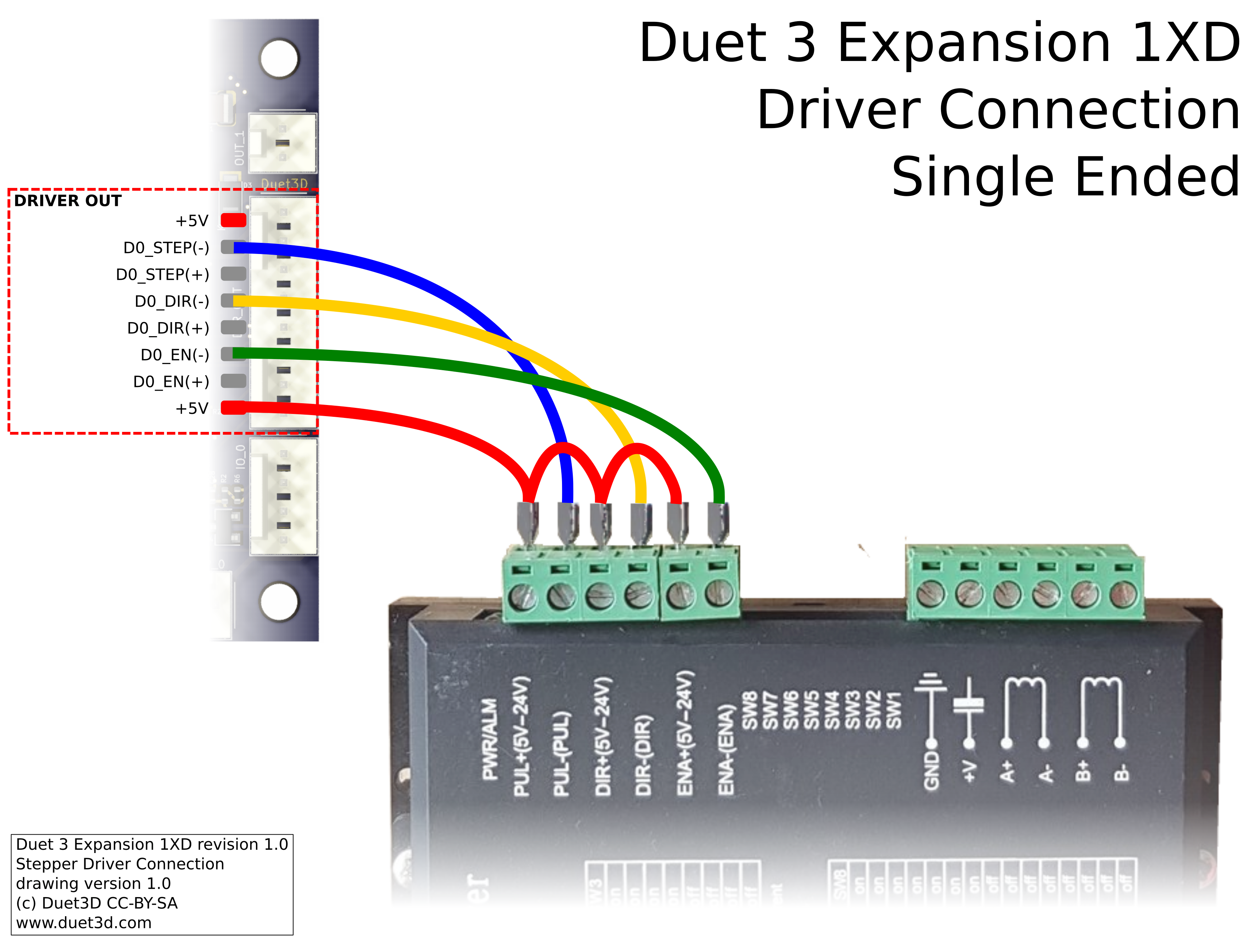
                    @dc42 It's a closed loop servo with an incremental type 2500-line quadrature encoder, 10,000 PPR.

                    I double checked the wiring (single ended mode) and everything looks OK but I'm still having trouble turning the servo.

                    http://www.leadshine.com/UploadFile/Down/ELD2-RS400 User Manual for overseas_20191226(V_1.02).pdf

                    Delta Printer Using a Duet 2 Wifi v1.04c, FW3.4.0beta2, Duet WiFi sever 1.26, Duet Web Control 3.3.0

                    undefined 1 Reply Last reply 3 Jul 2022, 03:10 Reply Quote 0
                    • undefined
                      ShaunCro @code7
                      last edited by 3 Jul 2022, 03:10

                      @code7

                      Your link doesn't work, and can't find it on the main leadshine site so here is the manualslib link

                      https://www.manualslib.com/products/Leadshine-Eld2-Rs400-11165537.html

                      Following this as I have to setup two EL5-400's soon with ACM604 motors.

                      Lets just get one thing straight....

                      You don't own a Delta! It's true, you don't!

                      It owns you!

                      undefined 1 Reply Last reply 3 Jul 2022, 05:39 Reply Quote 0
                      • undefined
                        code7 @ShaunCro
                        last edited by code7 7 Mar 2022, 05:40 3 Jul 2022, 05:39

                        @shauncro Thanks for adding a valid link to the manual. After reading through more of the manual I'm seeing how much more complex driving a servo is than a stepper.

                        If anyone can recommend a servo driver that you are having success driving with the 1XD please let me know as I am open to switching if it would simplify things.

                        Delta Printer Using a Duet 2 Wifi v1.04c, FW3.4.0beta2, Duet WiFi sever 1.26, Duet Web Control 3.3.0

                        undefined undefined 2 Replies Last reply 3 Jul 2022, 16:35 Reply Quote 0
                        • undefined
                          ShaunCro @code7
                          last edited by 3 Jul 2022, 16:35

                          @code7 I'll let you know how my setup goes, had them sitting in a box for a while, and finally have the time to get started. I'm running the 6HC though, so will be a bit different. Have you tried to use the leadshine tuning software?

                          Lets just get one thing straight....

                          You don't own a Delta! It's true, you don't!

                          It owns you!

                          undefined 1 Reply Last reply 6 Jul 2022, 16:20 Reply Quote 0
                          • undefined
                            Marcossf @code7
                            last edited by 4 Jul 2022, 07:46

                            @code7 We sucesfull use Oriental Motor AZD-K series absolute enconder pulse-input type motor driver with a 1XD board.
                            https://www.orientalmotor.eu/Products/Stepper_motors/Closed_loop_stepper_motor_packages/az_dc/?&filter1=Standard&filter2=60+mm&feld040=0&arid=22968&dwn=artnr

                            Config example:

                            ;######################### AXIS BOARD DRIVERS DECLARATIONS #########################
                            M569 P40.0 S1 ; physical drive 40 goes forwards X
                            M569 P41.0 S0 ; physical drive 41 goes backwards Y1
                            M569 P42.0 S0 ; physical drive 42 goes backwards Y2
                            M569 P43.0 S0 ; physical drive 43 goes backwards Z1 (Z)
                            M569 P44.0 S0 ; physical drive 44 goes backwards Z2 (U)
                            M569 P45.0 S0 ; physical drive 45 goes backwards Z3 (V)
                            ; ############################## DRIVER PARAMETERS SETTINGS ##############################
                            M584 X40.0 Y41.0:42.0 Z43.0 U44.0 V45.0 ; axis drive mapping
                            M350 X1 Y1 V1 Z1 U1 V1 I1 ; configure axis microstepping with interpolation
                            M92 X150.53 Y150.53 Z100.12 U100.12 V100.12 ; axis steps per mm
                            M566 X900.00 Y900.00 Z500.00 U500.0 V500.0 ; set maximum instantaneous speed changes (mm/min)
                            M203 X18000.00 Y18000.00 Z12000.00 U12000.00 V12000.00 ; set maximum speeds (mm/min)
                            M201 X300.00 Y300.00 Z500.00 U500.00 V500.00 ; set accelerations (mm/s^2)
                            ;################################# AXIS ENDSTOPS #################################
                            M574 X1 S1 P"!40.io0.in" ; configure active-high endstop for low end on X via pin 40.io0.in
                            M574 Y1 S1 P"!41.io0.in" ; configure active-high endstop for low end on Y via pin 41.io0.in
                            M574 Z2 S1 P"!43.io0.in"
                            M574 U2 S1 P"!44.io0.in" ; configure active-high endstop for high end on U via pin 44.io0.in
                            M574 V2 S1 P"!45.io0.in" ; configure active-high endstop for high end on V via pin 45.io0.in

                            1854b2c9-6e2d-4108-9d80-601fa42a0894-image.png

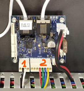
                            1 - Step area defined in the axis as virtual "endstop"
                            2 - Step and dir signals to motor driver

                            undefined 1 Reply Last reply 6 Jul 2022, 16:22 Reply Quote 1
                            • undefined
                              code7 @ShaunCro
                              last edited by 6 Jul 2022, 16:20

                              @shauncro Thanks for keeping me in the loop. I haven't tried the tuning software yet. Maybe once I get the closed loop servo turning.

                              Delta Printer Using a Duet 2 Wifi v1.04c, FW3.4.0beta2, Duet WiFi sever 1.26, Duet Web Control 3.3.0

                              1 Reply Last reply Reply Quote 0
                              • undefined
                                code7 @Marcossf
                                last edited by 6 Jul 2022, 16:22

                                @marcossf Thanks for the detailed recommendation. I'll check it out.

                                Delta Printer Using a Duet 2 Wifi v1.04c, FW3.4.0beta2, Duet WiFi sever 1.26, Duet Web Control 3.3.0

                                undefined 1 Reply Last reply 7 Jul 2022, 11:29 Reply Quote 0
                                • undefined
                                  dc42 administrators @code7
                                  last edited by 7 Jul 2022, 11:29

                                  @code7 please share your config.g file.

                                  Which axis do you want to drive with this servo motor?

                                  Duet WiFi hardware designer and firmware engineer
                                  Please do not ask me for Duet support via PM or email, use the forum
                                  http://www.escher3d.com, https://miscsolutions.wordpress.com

                                  1 Reply Last reply Reply Quote 0
                                  • undefined
                                    code7
                                    last edited by code7 7 Jul 2022, 17:29 7 Jul 2022, 17:14

                                    @dc42 The closed loop servo is on drive 122.0 on the 1XD Exp Board. I'm able to turn the motor briefly until I receive the "Motor speed out of control" Alarm from the ELD2 servo driver.

                                    This is how I have it wired:
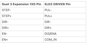
                                    49112e3c-9025-41f7-95ee-935495569bc7-image.png

                                    ELD2 Manual:
                                    http://leadshineusa.com/UploadFile/Down/ELD2-RS70-- User Manual_2021_Ver1.09.pdf

                                    Config:

                                    G4 S2 ; wait a moment for the CAN expansion boards to start
                                    ; Drives
                                    M569 P0.0 S0 ; physical drive 0.0 goes backwards
                                    M569 P0.1 S0 ; physical drive 0.1 goes backwards
                                    M569 P0.2 S1 ; physical drive 0.2 goes forwards
                                    M569 P122.0 S0 ; physical drive 121.0 goes backwards
                                    M584 X0.0 Y0.1 Z0.2 E122.0 ; set drive mapping
                                    M350 X16 Y16 Z16 E1 I1 ; configure microstepping with interpolation
                                    M92 X80.00 Y80.00 Z400.00 E100.00 ; set steps per mm
                                    M566 X1200.00 Y1200.00 Z24.00 E300.00 ; set maximum instantaneous speed changes (mm/min)
                                    M203 X9000.00 Y9000.00 Z360.00 E6000.00 ; set maximum speeds (mm/min)
                                    M201 X500.00 Y500.00 Z100.00 E5000.00 ; set accelerations (mm/s^2)
                                    M906 X800 Y800 Z800 E1200 I50 ; set motor currents (mA) and motor idle factor in per cent
                                    M84 S30 ; Set idle timeout
                                    ; Axis Limits
                                    M208 X0 Y0 Z0 S1 ; set axis minima
                                    M208 X235 Y235 Z260 S0 ; set axis maxima
                                    ; Endstops
                                    M574 X1 S1 P"io1.in" ; configure switch-type (e.g. microswitch) endstop for low end on X via pin io1.in
                                    M574 Y2 S1 P"io2.in" ; configure switch-type (e.g. microswitch) endstop for high end on Y via pin io2.in
                                    M574 Z1 S1 P"io3.in" ; configure switch-type (e.g. microswitch) endstop for low end on Z via pin io3.in
                                    ; Z-Probe
                                    M558 P0 H5 F120 T6000 ; disable Z probe but set dive height, probe speed and travel speed
                                    M557 X15:215 Y15:195 S20 ; define mesh grid
                                    ; Heaters
                                    M308 S0 P"temp0" Y"thermistor" T100000 B4092 ; configure sensor 0 as thermistor on pin temp0
                                    M950 H0 C"out0" T0 ; create bed heater output on out0 and map it to sensor 0
                                    M307 H0 B1 S1.00 ; enable bang-bang mode for the bed heater and set PWM limit
                                    M140 H0 ; map heated bed to heater 0
                                    M143 H0 S150 ; set temperature limit for heater 0 to 150C
                                    M308 S1 P"temp1" Y"thermistor" T100000 B4092 ; configure sensor 1 as thermistor on pin temp1
                                    M950 H1 C"out1" T1 ; create nozzle heater output on out1 and map it to sensor 1
                                    M307 H1 B0 S1.00 ; disable bang-bang mode for heater and set PWM limit
                                    M143 H1 S275 ; set temperature limit for heater 1 to 275C
                                    ; Fans
                                    M950 F0 C"!out3" Q500 ; create fan 0 on pin !out3 and set its frequency
                                    M106 P0 S0 H-1 ; set fan 0 value. Thermostatic control is turned off
                                    M950 F1 C"!out4" Q500 ; create fan 1 on pin !out4 and set its frequency
                                    M106 P1 S1 H1 T45 ; set fan 1 value. Thermostatic control is turned on
                                    M950 F2 C"out5" Q500 ; create fan 2 on pin !out5 and set its frequency
                                    M106 P2 S1 H-1 ; set fan 2 value. Thermostatic control is turned off
                                    ; Tools
                                    M563 P0 S”Servo Extruder” D0 F0 ; define tool 0
                                    G10 P0 X0 Y0 Z0 ; set tool 0 axis offsets
                                    G10 P0 R0 S0 ; set initial tool 0 active and standby temperatures to 0C
                                    M563 P1 S”Tool1” F-1 ; define tool 1
                                    G10 P1 X0 Y0 Z0 ; set tool 1 axis offsets
                                    G10 P1 R0 S0 ; set initial tool 1 active and standby temperatures to 0C
                                    ; Miscellaneous
                                    T0 ; select first tool

                                    Delta Printer Using a Duet 2 Wifi v1.04c, FW3.4.0beta2, Duet WiFi sever 1.26, Duet Web Control 3.3.0

                                    jay_s_ukundefined undefined 2 Replies Last reply 7 Jul 2022, 17:36 Reply Quote 0
                                    • jay_s_ukundefined
                                      jay_s_uk @code7
                                      last edited by 7 Jul 2022, 17:36

                                      @code7 you don't appear to have any driver timing on your M569. External drivers usually can't keep up the same way internal ones can. Try something like T5:5:10:10 as a first shout

                                      Owns various duet boards and is the main wiki maintainer for the Teamgloomy LPC/STM32 port of RRF. Assume I'm running whatever the latest beta/stable build is

                                      1 Reply Last reply Reply Quote 1
                                      • undefined
                                        ShaunCro @code7
                                        last edited by 8 Jul 2022, 23:42

                                        @code7

                                        You need to choose whether you going to run high or low on the step/dir.

                                        So typically you daisy chain the positive from the 5V+ and the have the Negative as the pulse input, so only they get connected to the corresponding pins. ENA is typically left unconnected from the documentation I have read on my drivers.

                                        f46c9ae1-e4f5-465b-ae08-5d9b8ce3996c-image.png

                                        I assume your driver also has a 25\26 pin D-Sub interface, if so, you only need to connect up the corresponding wires and leave the rest, as they aren't used in our instance. But, you may need to grab the software from leadshine to change a few parameters and ensure they are funning step/dir and not RS485 for communication.

                                        Lets just get one thing straight....

                                        You don't own a Delta! It's true, you don't!

                                        It owns you!

                                        undefined 1 Reply Last reply 9 Jul 2022, 04:05 Reply Quote 0
                                        • undefined
                                          ShaunCro @ShaunCro
                                          last edited by 9 Jul 2022, 04:05

                                          @shauncro Nope, if I look at my user manual, I need a bit more. Fiddling and will post a bit later what I happen upon. But still getting everything up and running.

                                          Lets just get one thing straight....

                                          You don't own a Delta! It's true, you don't!

                                          It owns you!

                                          undefined 1 Reply Last reply 10 Jul 2022, 00:11 Reply Quote 0
                                          11 out of 41
                                          • First post
                                            11/41
                                            Last post
                                          Unless otherwise noted, all forum content is licensed under CC-BY-SA