Mesh Compensation active but still uneven first layer
-
Trying to figure out why my first layer is uneven, after I had run the mesh compensation
Using Euclid probe which gives very reliable results
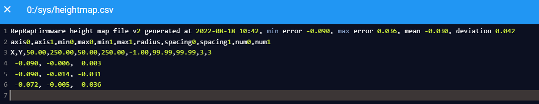
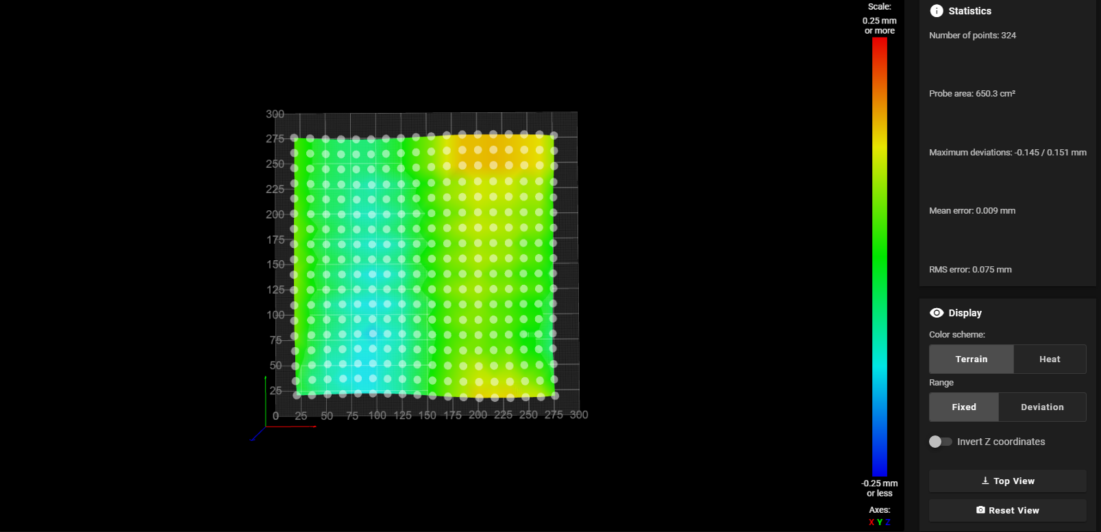
using fine grid of 15mmHere is my mesh
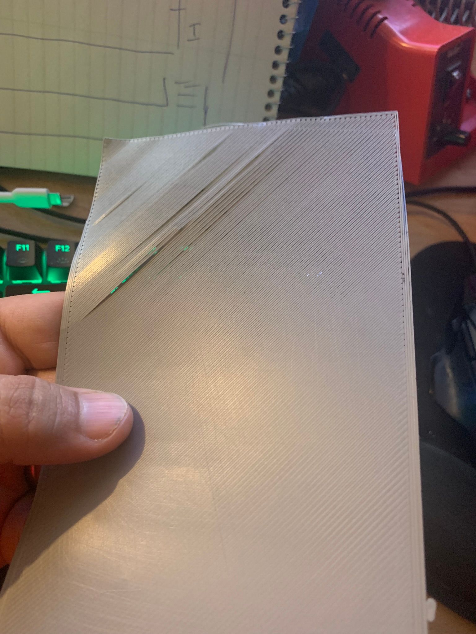
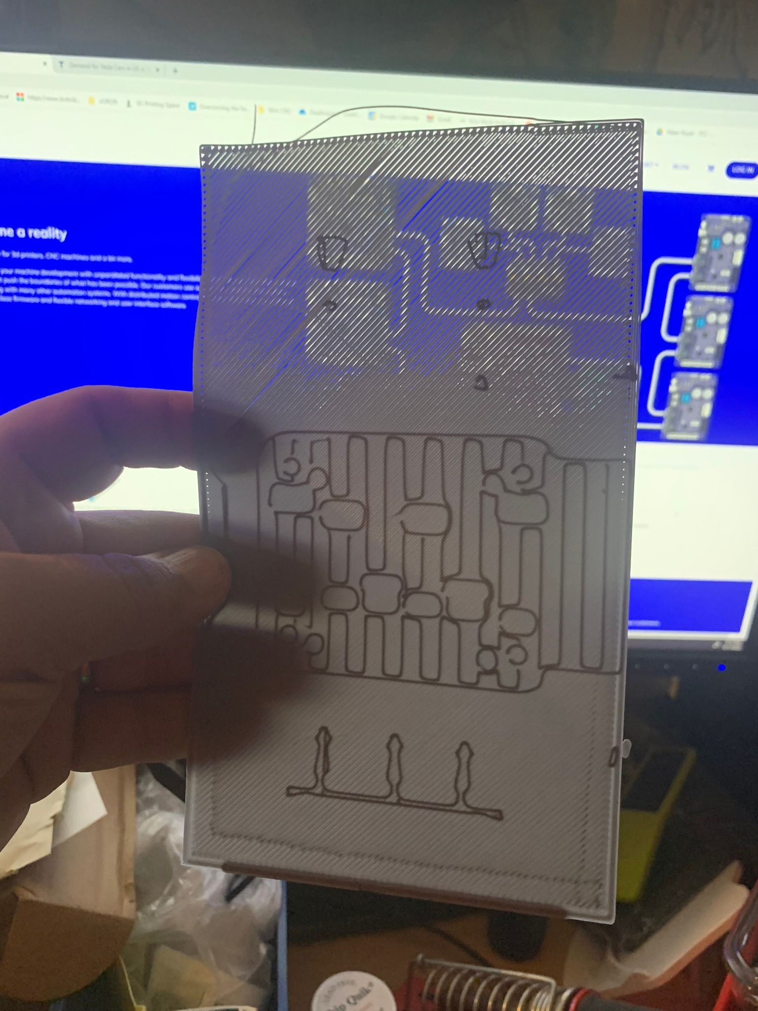
Here is my print
-
@adamfilip 2nd attemp. new mesh generated., similar results
This is my start up gcode
G90 ; use absolute coordinates
M83 ; extruder relative mode
M140 S{first_layer_bed_temperature[0]} ; set final bed temp
G28 ; home all axis
G29 S1 ;LOAD MESH 1
;G1 Z30 F240
G1 X20 Y20 F3000
M104 S{first_layer_temperature[0]} ; set final nozzle temp
;M190 S{first_layer_bed_temperature[0]} ; wait for bed temp to stabilize
M109 S{first_layer_temperature[0]} ; wait for nozzle temp to stabilize
M564 S0 H0		;Free Movement
M104 S220 ; set final nozzle temp
M109 S220 ; wait for nozzle temp to stabilize
G1 Z8 F500	;Move Z to position
G1 X192 Y-20 F1500			;Move to Bucket Position
G1 E20 F500 ; prime the nozzle
M400
G1 E-0.5 F3600 ; retract 0.5mm
G1 X130 Y-20 F4000	; bruh start postion
G1 X80 Y-20 F4000	; bruh end postion
G1 Y-15 F4000	; bruh start postion
G1 X90	F4000 	;move right 10
G1 Y-20 F4000	;Move forward 5
G1 X100	F4000 	;move right 10
G1 Y-15 F4000	;Move back 5
G1 X110	F4000 	;move right 10
G1 Y-20 F4000	;Move forward 5
G1 X120	F4000 	;move right 10
G1 Y-15 F4000	;Move back 5
G1 X130 Y-17.5 F4000	; bruh start postion
G1 X70 Y-17.5 F4000	; bruh end postion
G1 Z20 F240					;Move Z to position
G1 X70 Y0 F2000	; move over bed
M564 S1 H0		;Limit Movement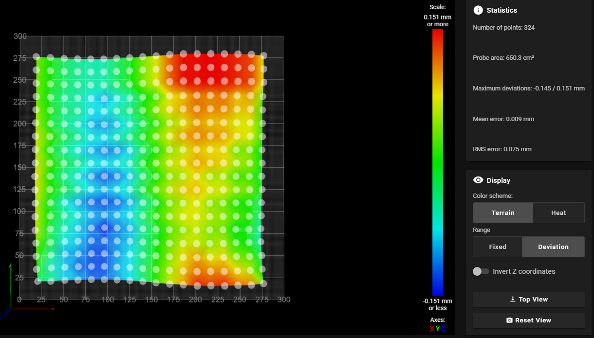

my config
;389.86; Configuration file for Duet WiFi (firmware version 3) ; executed by the firmware on start-up ; ; generated by RepRapFirmware Configuration Tool v2.1.5 on Wed Jan 08 2020 19:38:55 GMT-0500 (Eastern Standard Time) ; General preferences ;M564 H0 ; allow movement without homing G90 ; send absolute coordinates... M83 ; ...but relative extruder moves M550 P"TitanXY" ; set printer name M929 S3 ;Log console to SDCard M669 K0 ; Motion Kinematics for Cartesian mode ; Network M552 S1 ; enable network M586 P0 S1 ; enable HTTP M586 P1 S0 ; disable FTP M586 P2 S0 ; disable Telnet M586 P1 S1 C"*" ; allows Cross Origin Resource Sharing (CORS). ; --- drive map --- ; _______ 300,300 ; | V6 | W7 | ; | ----- | ; | U5 | Z8 | ; 0,0 ------- ; front ; Drives M569 P0 S0 ; X Motor physical drive 0 goes backwards previously P0 M569 P1 S1 ; Y Motor M569 P3 S1 ; E0 Extruder physical drive 3 goes Forwards M569 P5 S0 ; FRONT LEFT Z Drive 5 on Duex 5 0.10 M569 P6 S1 ; REAR LEFT Z Drive 6 on Duex 5 0.10 M569 P7 S1 ; REAR RIGHT Z Drive 7 on Duex 5 0.10 M569 P8 S0 ; FRONT RIGHHT Z Drive 8 on Duex 5 0.10 ;M584 X0 Y1 U5 V6 W7 Z8 E3 ; TEST MAPPING M584 X0 Y1 Z5:6:7:8 E3 ; MOTOR MAPPING WITH 4 Z STEPPERS M350 X16 Y16 Z16 I1 ; configure microstepping without interpolation, previously 32 M350 E16 I1 ; configure microstepping with interpolation ;M92 X80.09 Y80.28 Z321.62 E397 ; set steps per mm. M92 X80.09 Y80.06 Z643.24 E397 ; july 21 set steps per mm M566 X900 Y900 Z60 E800 ; Set maximum instantaneous speed changes (mm/min) JERK M203 X18000 Y18000 Z3000 E2500 ; Set maximum speeds (mm/min) M201 X2000 Y2000 Z250 E1000 ; Set accelerations (mm/s^2) M906 X1000 Y1000 Z600 E900 I30 ; Set motor currents (mA) and motor idle factor in per cent X1400 Y1400 Z1300 M204 P1500 T2000 ; Set printing acceleration and travel accelerations M84 S30 ; Set idle timeout M572 D0 S0.025 ; Pressure Advance ; Axis Limits M208 X0 Y0 Z0 S1 ; set axis minima M208 X300 Y300 Z550 S0 ; set axis maxima. ;SKEW COMPENSATION . ;M556 S100 X-0.2 M556 S100 X-0.313 ;july 21 ;911 PRINT RECOVERY MODE M911 S19.8 R22.0 P"M913 X0 Y0 G91 M83 G1 Z1 E-5 F1000" ; Endstops M574 X2 S1 P"!xstop" ; X max active high endstop switch M574 Y2 S1 P"!ystop" ; Y max active high endstop switch ;M591 D0 P3 C"e0stop" S1 E3 ; filament monitor connected to E0_stop M591 D0 ; display filament sensor parameters for extruder drive 0 ;M574 Z0 P"nil" ; zstop is free ;M950 J1 C"!zstop" ; Use Z endstop as Emergency Stop if Triggers, due to head Plunge M581 P1 T0 S1 R0 ;Euclid Settings M574 E1 S2 ;configure Z-probe endstop for low end on Z ; M558 K0 P5 C"^zprobe.in" H10 F500 60 T9000 A2 S0.02 ; K0 for probe 0, P5 for NC switch, C for input pin, ; ^ for enabling the native pullup resistor on Duet 2 ; hardware running RRF3 ; H dive height of 8mm, F300 probing speed 6mm/sec, ; T9000 travel speed 150mm/sec, ; A3 number of probes 1, S0.01 max tolerance of 0.01 G31 K0 P500 X0 Y-39 Z2.10 ; CHECK for LOOSE things first! set Z probe trigger ; value, offset and trigger height. Higher numbers ; makes nozzle closer to bed ; switch plunger is 16.4mm to the LEFT and 29.27mm in ; FRONT of the nozzle. Switch triggers 0.9mm BELOW nozzle ; https://duet3d.dozuki.com/Wiki/Test_and_calibrate_the_Z_probe#Secti ; Bed leveling ; --- drive map --- ; _______ 300,300 ; | V6 | W7 | ; | ----- | ; | U5 | Z8 | ; 0,0 ------- ; front M671 x-76:-76:382:382 Y-37:421:421:-37 S40 ; Define Z belts locations (Front_Left, Back_Left, Back_Right, Front_Right), S10 = MAX 10MM DIFFERENCE ALLOWED ;M671 x15:15:298:298 Y15:298:298:15 S20 ; Define Z belts locations (Front_Left, Back_Left, Back_Right, Front_Right), S10 = MAX 20MM DIFFERENCE ALLOWED M557 X20:280 Y20:280 S25 ; define mesh grid S86 = Spacing 86mm M376 H10 ; taper bed levelling off after 10mm height M581 ;Accelerometer M955 P0 C"spi.cs4+spi.cs3" I60 ;M593 P"zvdd" F34 ;INPUT SHAPER PROFILE ; Heaters M308 S0 P"bedtemp" Y"thermistor" T100000 B4138 ; configure sensor 0 as thermistor on pin bedtemp M950 H0 C"bedheat" T0 ; create bed heater output on bedheat and map it to sensor 0 M140 H0 ; Map heated bed to heater 0 M143 H0 S120 ; set temperature limit for heater 0 to 120C ;M307 H0 R0.668 K0.284:0.000 D5.21 E1.35 S1.00 B0 ; PID BED Tuning M307 H0 R0.671 K0.370:0.000 D6.13 E1.35 S1.00 B0 M308 S1 P"e0temp" Y"thermistor" T100000 B4725 C7.060000e-8 ; configure sensor 1 as thermistor on pin e0temp M950 H1 C"e0heat" T1 ; create nozzle heater output on e0heat and map it to sensor 1 M143 H1 S300 ; set temperature limit for heater 1 to 300C M307 H1 R4.107 K1.013:0.000 D1.94 E1.35 S1.00 B0 V24.0 ;REVO 24V M308 S2 P"e1temp" Y"thermistor" T100000 B3950 ; configure sensor 2 as thermistor on pin e1temp M950 H2 C"e1heat" T2 ; create chamber heater output on e1heat and map it to sensor 2 M307 H2 B0 S1.00 ; disable bang-bang mode for the chamber heater and set PWM limit M141 H2 ; map chamber to heater 2 M143 H2 S100 ; set temperature limit for heater 2 to 100C ; Fans M950 F0 C"fan2" Q500 ;create fan 2 on pin fan0 and set its frequency M106 P0 S0 H-1 ; set fan 0 value. Thermostatic control is turned off ; Tools M563 P0 D0 H1 F0 ; define tool 0 ;M563 P1 D1 H2 F1 ; define tool 1 G10 P0 X0 Y0 Z0 ; set tool 0 axis offsets G10 P0 R0 S0 ; set initial tool 0 active and standby temperatures to 0C M17 Z ;engage z stepper to prevent gantry falling -
@adamfilip wonder if using the command in my start code
M564 S1 H0 ;Limit Movementis messing with the Mesh Compensation
-
@adamfilip just thinking out loud but looking at this map
when printing in the Blue are the first layer is too close. and when printing in the red area. the first layer is too high, which sounds like the complete opposite of what should be happening.
could it be applying the compensation in reverse??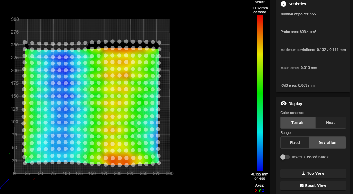
-
my machine is similar to Voron 2.4 with 4 point gantry levelling and a fixed bed
This is the homing /Startup sequence
Home Z
G29 S2											;DISABLE BED COMPENSATION
if !move.axes[0].homed || !move.axes[1].homed     ; If the printer hasn't been homed, home it
   M98 P"0:/sys/homexy.g"
M561                                            ; clear any bed transform
M290 S0 R0                                      ; clear baby steps
G91                                             ; relative positioning
G1 H2 Z6 F6000                                  ; lift Z relative to current position to clear any obstructions
M400
G90                                             ; absolute positioning
M401 P0                                         ; This runs macro file deployprobe
G1 X150 Y190 F9000                            ; go to center of bed in advance of probe that point
M400
G30                                             ; Probe the bed at the current XY position. When the probe is triggered, Datum Z0
G1 Z10                                          ; raise Z=10
M400
G4 P500
M98 P"0:/sys/bed4point.g"                       ; tram gantry - Like G32

G1 X150 Y190 F9000                            ; go to center of bed in advance of probe that point
M400
G30   											;probe z point
M402 P0                                         ; retract probe
G1 Z10 F600                                     ; lift Z relative to current position
G90                                             ; absolute positioning

G29 S1											;LOAD MESH COMPENSATION
4 Point Gantry levelling is also called and does this
M558 F800 A1 H15 ; fix probe speed to 3mm/s, Height 10mm G90 G4 P250 M561 ; Clear any bed transform G30 P0 X25 Y15 Z-99999 ; probe near a leadscrew G30 P1 X25 Y250 Z-99999 ; probe near a leadscrew G30 P2 X285 Y250 Z-99999 ; probe near a leadscrew G30 P3 X285 Y15 Z-99999 S4 ; probe near a leadscrew and calibrate 4 motors M558 F200 A2 H6 ; fix probe speed to 3mm/s, Height 10mm G30 P0 X25 Y15 Z-99999 ; probe near a leadscrew G30 P1 X25 Y250 Z-99999 ; probe near a leadscrew G30 P2 X285 Y250 Z-99999 ; probe near a leadscrew G30 P3 X285 Y15 Z-99999 S4 ; probe near a leadscrew and calibrate 4 motors M558 H10 F500 60 T9000 A1 S0.02 ; reset probe setting to normal -
@adamfilip could anything stop the compensation from moving Z in negative? I assume even machine limits . are ignored
-
@adamfilip You could try allowing small negative movements to see if it makes any difference, but looking at your mesh, would any compensation require a movement below zero from say a 0.2mm layer height?
Some thoughts and suggestions on your problem....
Was the bed heated when you created the mesh? Could the shape of the bed (or any flex plate), be changing due to differences between probing and printing (like temperature)?
Are your probe offset settings correct? From your config.g it seems like the probe position is offset 39mm from the nozzle, but the comment next to the setting seems to say it is actually 16.4mm left and 29.27mm in front of the nozzle (which does not match the setting). If the probe offsets re wrong then the wrong part of the mesh will be being used to perform corrections.
The usual cause of problems like this seems to be due to a mechanical issue. This is particularly true when the probe is offset from the nozzle. When you have an offset like this then a small twist to the frame can result in the sort of issues you are seeing (because in effect the Z offset of the probe is different at different X/Y locations due to the twist). Another possible cause is that as the probe is moved around the bed then cables or other attachments to the probe/print head apply a force to the print head causing small movements (which get amplified by the probe offset).
You can check for the above by manually probing different points on the bed. Simply set up the bed the same way you did when creating the mesh (so heated up if you had heaters on when probing), make sure mesh compensation is turned off, then move the nozzle so that it is at the same location as one of your probe points lower the nozzle until it just touches a feeler gauge (or sheet of paper if you don't have a feeler gauge). make a note of the Z height and repeat at other points in the mesh. Then compare the heights obtained with the ones in your mesh file. If all is well they should match closely (with a constant offset that matches your gauge height). If you find that they vary over the bed then this probably indicates some sort of mechanical problem. This is best done with a nozzle without filament and that has been cleaned (to provide as "clean" a surface as possible when manually probing).
If you search the forum you may find other suggestions as this sort of issue seems to come up fairly often.
-
@gloomyandy Thanks for your reply
How would i allow a negative movement?
Bed was heated for 10min prior to doing a mesh
bed is very flat and stiff its using a 1/2" MIC6 Cast Alum bed + 1/16" FR4 Top Sheet thats held down on all sidesI would ignore some of the config.g comments, as they are not updated. the offset actual set is correct X0, X-39
Gantry has 4 motors that do tramming to bed, first (Like Voron)I have proper cable routing on my print head, so cables are not affecting the probe position as far as I can tell.
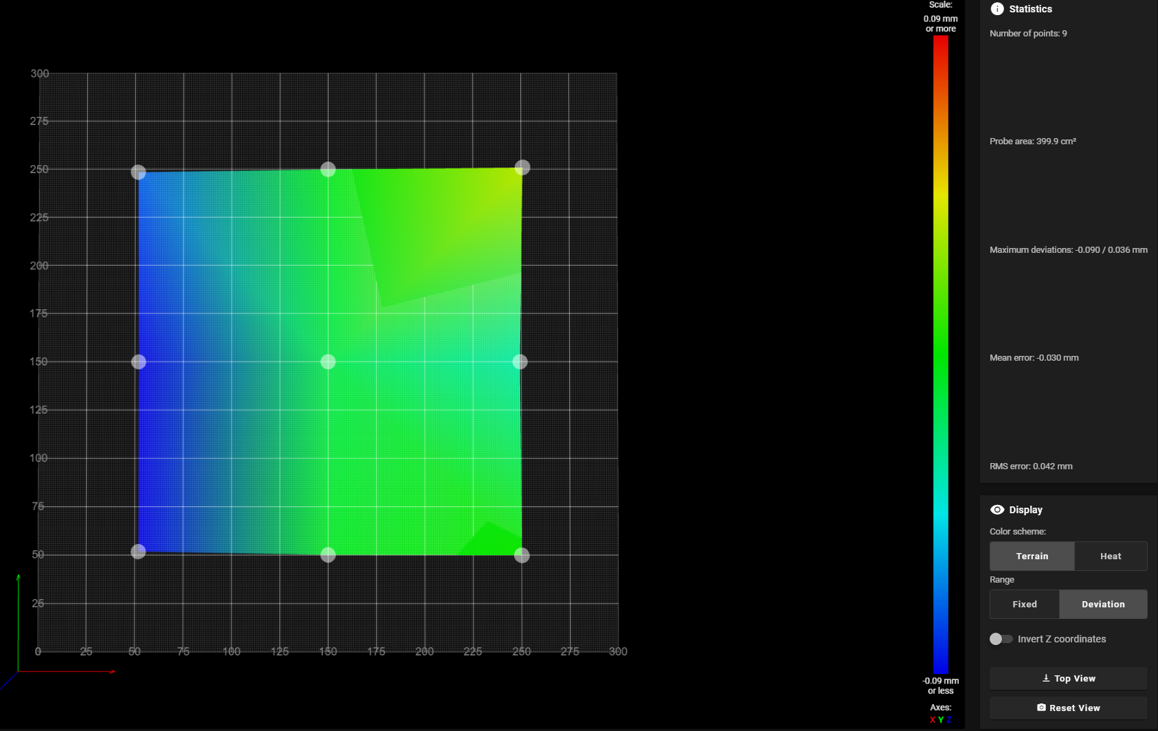
I have been searching this forum and also google searching to try and find an answer. ive tried dense meshes and grids with only 9 points (3x3) results are similar. Tried with no taper, with 3mm and with 10mm, same result.
Motion system and frame on my machine are quite ridgid, spent alot of time making this machine solid, id be surprised if it was a mechanical issue at this point.
-
@gloomyandy Here is a video to show how my machine is setup and how homing works on it
-
-
-
@adamfilip You allow a -ve movement by specifying a -ve value for the lower limit of Z in the M208 command. But if the maximum -ve value in your mesh is less than your first layer height (say 0.2mm), then mesh compensation will not need to move below Z=0, so even if the firmware was limiting the -ve movement it should not be an issue. If you do allow movement below Z=0 then take care because that may allow the nozzle to hit the bed.
I'm sure your machine is well built, but it only takes a very small twist to cause problems. I'd really recommend trying the test I have described above. It will allow you to get a better feel for how your printer is working and the shape of the bed. It is tedious but usually worth the effort.
Have you tried printing with the mesh disabled? That will also give you a good idea of the actual shape of the bed (as seen by the nozzle) and would also be a good way to check how well the probing you have matches the actual bed shape.
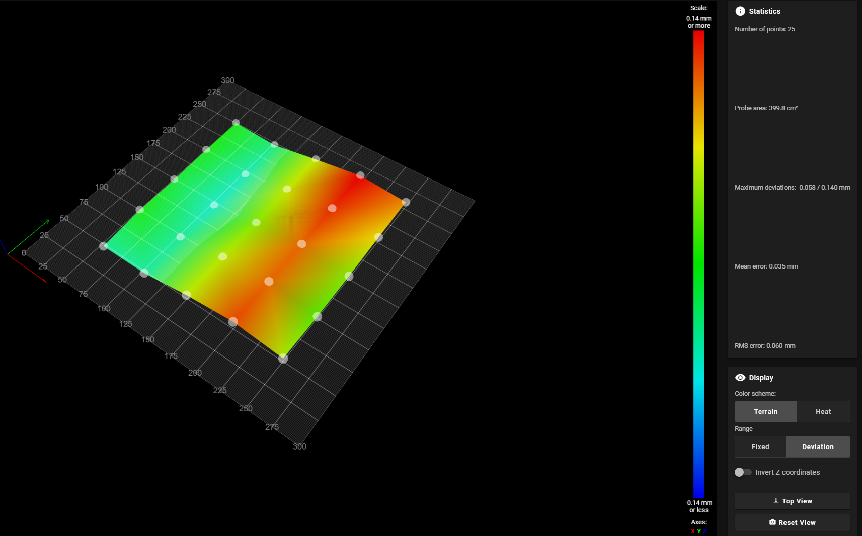
Your mesh seems to show a ripple, if you rotate the FR4 surface through 90 degrees does the ripple change with it?
One final point, I'd strongly recommend homing Z such that the X/Y position of the probe matches exactly one of your probe points. If you do that, then the selected point should always be very close to 0 in the mesh. Having a point like this allows you to do a quick sanity check on the mesh, to ensure that nothing "odd" is happening with it.
-
@gloomyandy I did three tests
genered 3 new meshes using ProbeAlum Bed with FR4 Sheet
Alum Bed with FR4 Sheet turned 90 degrees counter clockwise

Alum Bed without FR4 Sheet

-
@adamfilip
Basically the same image, although the print bed has been rotated.
If you have a straightedge, check your x-axis.
It looks like it is not straight but has a wave.Google Translate
--- Original Text ---Im Grunde genommen das gleiche Bild, obwohl das Druckbett gedreht wurde.
Wenn Du ein Haarlineal hast, dann prüfe mal Deine X-Achse.
Es sieht so aus als wäre sie nicht gerade sondern hat eine Welle. -
@adamfilip said in Mesh Compensation active but still uneven first layer:
M558 K0
You only have a single probe, so remove the K0. When you change settings in your other macros you don't include K0 to target the probe so some settings may be getting reset or misapplied.
So either remove the K0, or use it consistently and re-create your mesh.
-
I dont see how it would be possible for the X or Y axis to not be straight, using 20x20 Vslot alum extrusion, and using Exoslide Carriages, the motion is smooth, it would bind if it has a bend in it. extrusion is generally super straight. I really dont think this is the issues here
-
@adamfilip
If you turned the FR4 plate by 90° and the mesh looks almost the same, then it can only be because of the X-axis.
A mirror is generally one of the flattest surfaces, if you have a mirror the size of your print bed then create a mesh with it.
If it looks the same as the previous meshes, then the aluminum profile must have a wave.While it won't have anything to do with the apparently flipped heightmap, it does explain the almost identical meshes of the three measurements you took.
Google Translate
--- Original Text ---Wenn Du die FR4 Platte um 90° gedreht hast und das Mesh sieht fast gleich aus, dann kann es ja nur an der X-Achse liegen.
Ein Spiegel ist im allgemeinen eines der ebensten Oberflächen, wenn Du einen Spiegel in der Größe Deines Druckbettes hast, dann erstelle damit mal ein Mesh.
Sollte es gleich aussehen wie die vorherigen Meshes, dann muss das Alu-Profil eine Welle haben.Es wird zwar nichts mit der anscheinend umgedrehten Heightmap zutun haben, aber es erklärt die fast identischen Meshes der drei Messungen die Du gemacht hast.
DDA5X... 0.9° Stepper... Linearrails... Duet 2 Wifi... PT100 Board... Duet IR-Probe... Dyze Pro Kit up to 500°C.. etc
Thingiverse -
@norder When I choose a homiung point that represented the lowest point on the bed. so it didnt go into negatives when I did the mesh levelling, it worked fine.
choosing a homing point thats higher than the lowest point, seems to be messing up mesh compensation.
-
@adamfilip said in Mesh Compensation active but still uneven first layer:
choosing a homing point thats higher than the lowest point, seems to be messing up mesh compensation.
The points are relative to the Z0 point and it can go below the zero point no problem.
-
@phaedrux But yet it wasnt.