Square shaped effector = easy toolchanger?
-
Hi gents,
I recently stumbled across Nicholas Sewards Wall mount Delta from 2015.
It has some designflaws, but there is one intriguing detail, I want to discuss here:
the square shaped effector
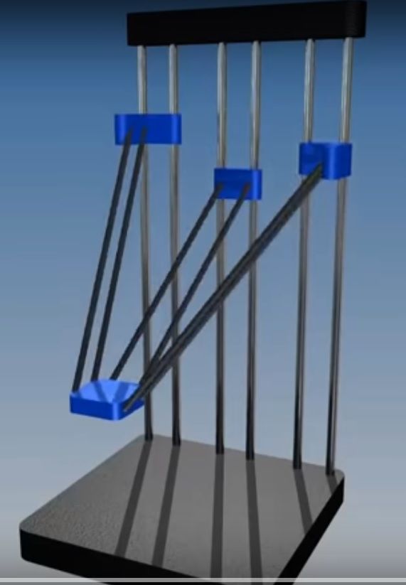
Because the effector has one open side, it could be build "U-shaped" , which would allow for easy toolchanging.
Now, if we would skip the idea of wall mounting, we could move the two outer towers to the front. Almost like a common delta, but still with a square effector.
That will eliminate the biggest flaw, but would still work with RRF Delta kinematics, right?Insane or intriguing, what's your opinion?
-
@o_lampe
It would also be a good candidate for direct driving with a geared extruder, like Orbiter or LGX light. Just let the motor stick out to the free side... -
@o_lampe see also this square delta thread https://groups.google.com/g/deltabot/c/INiYbXKw84s.
Duet WiFi hardware designer and firmware engineer
Please do not ask me for Duet support via PM or email, use the forum
http://www.escher3d.com, https://miscsolutions.wordpress.com -
@dc42 Thanks for the link, it was an interesting flashback to 2015-problems regarding V-rollers and bowden drive issues.
I'll use mgn12 rails and magballs, hope I can sort out some problems with that setup right away...Only have a sketch, but my approach will have equal angles, since I can move X&Y towers.
-
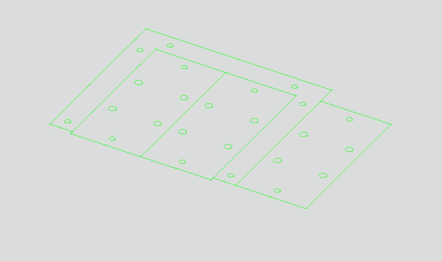
Today I started to sketch the U-shaped effector and MGN12 carriers with freeCAD, which is completely new to me. After hours, I finally managed to draw a fully constrained sketch, but somehow I still couldn't "extrude" it. It seems to miss some reference to the body?!
Anyway, too tired to read another tutorial I exported it as DXF file and Inkscaped it to cut it out with my laser.It's just a basic shape with the common 55/12mm magball pattern from the smart effector.
-
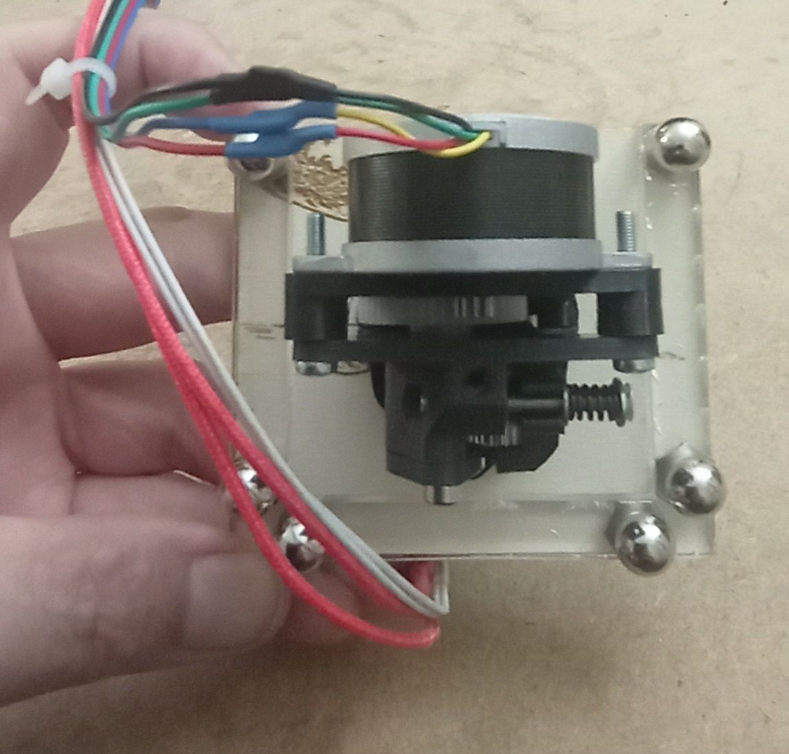
The first tool in the U-frame fits easily. An Orbiter would fit too without interfering the rods.
Lot's of room for fans and Z-probe underneath.
For now the tool isn't changeable, but for testing the square frame it's a start.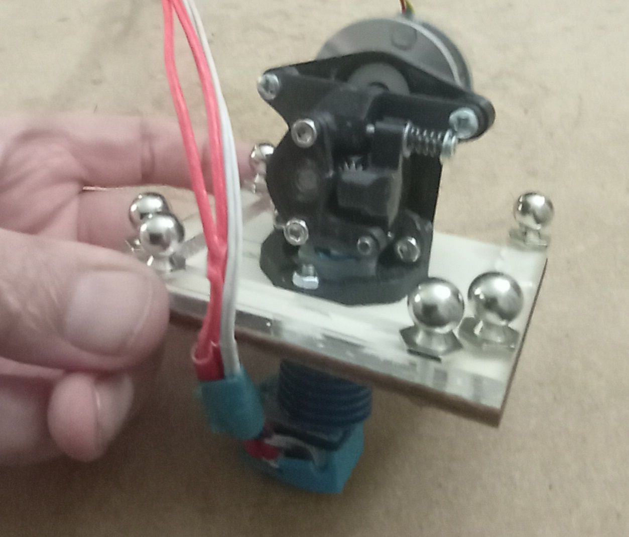
-
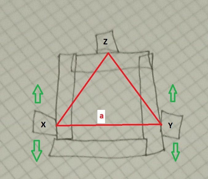
I cobbled together a square frame and manually moved the effector around.
It's rock solid around the Y-axis, but when the Z-tower (left one in the pic) reaches a flat angle, I can tilt the effector around X.
I was wondering, if I could use longer rods for the Z-tower to avoid flat angles, but that would cause unequal endstop positions for homing.
The best way to cope with that is to use longer rods for all towers and sacrifice printable height.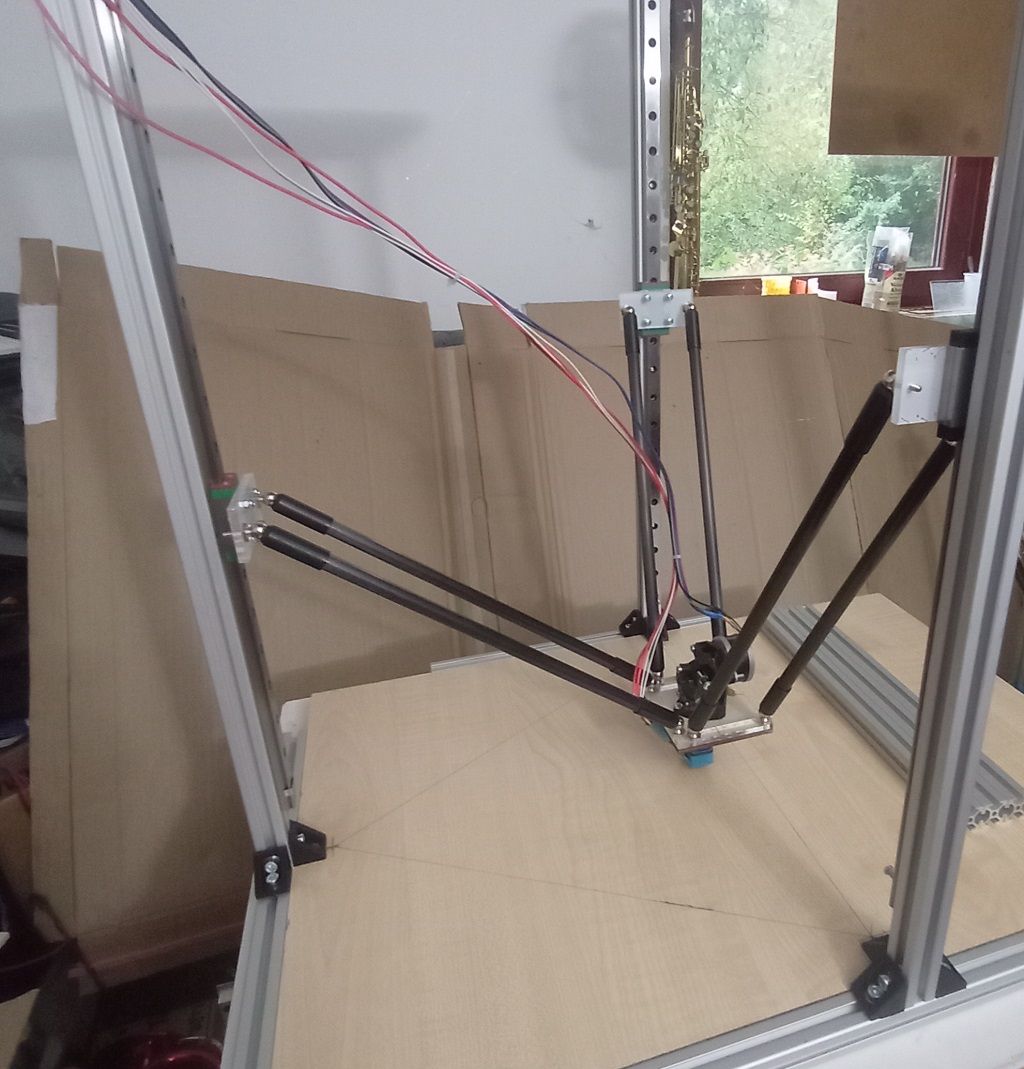
-
@o_lampe should that matter? The firmware can handle different effector rod lengths
-
@jay_s_uk That's true, but max. printable height would still be determined by the longest rods, right? I'll try it, just out of curiosity.
-
Let's get crazy!
The X&Y rods don't contribute to stability around the Y-axis right now.
I could take an extra step and turn these towers outwards.
That would be a parallelogram with a very wide open side...
The tower position would be closer to the Z-tower, just as it was in Sewards wall mount delta
I could even add a fourth (passive) tower that also works as parking lot for the tools.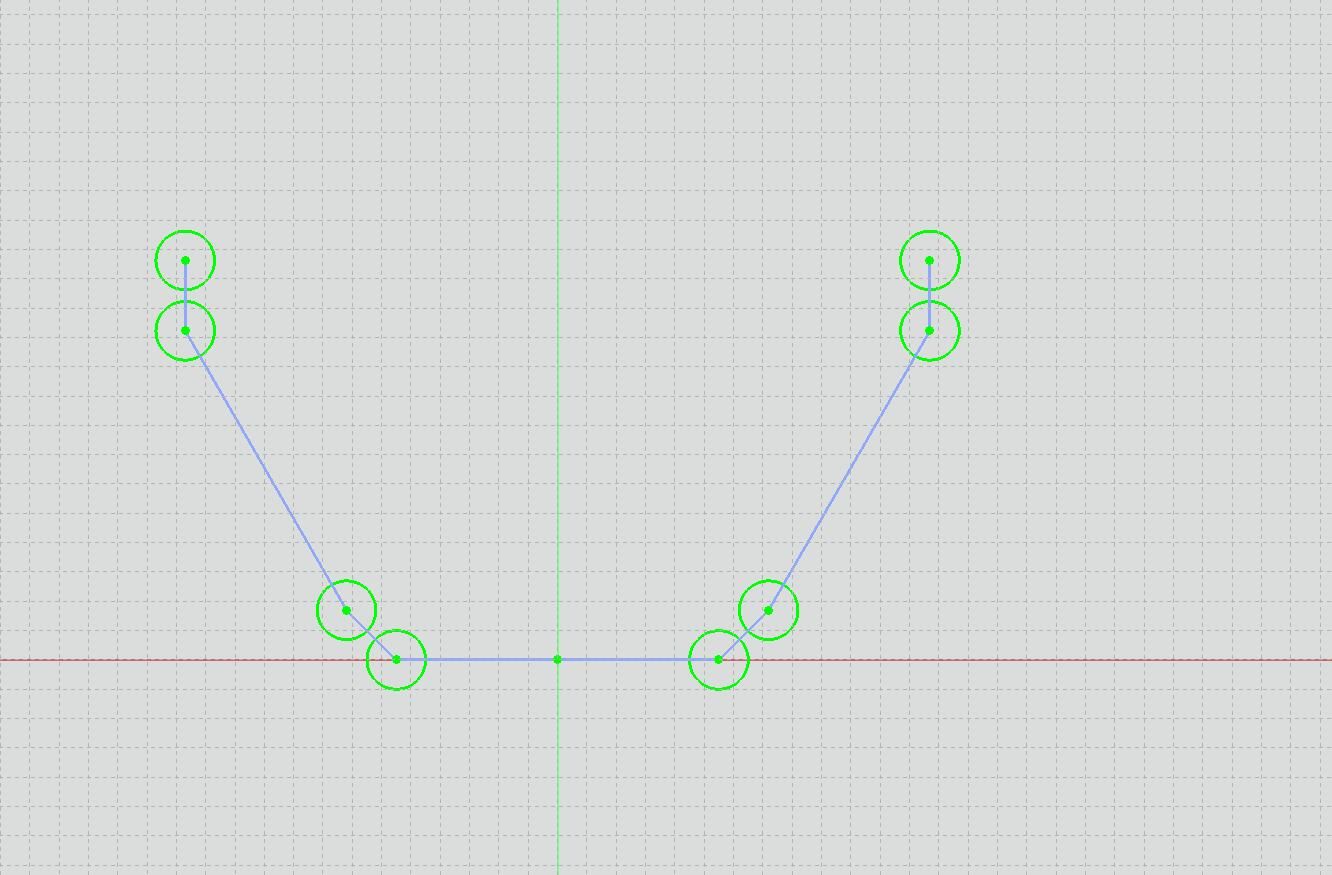
-
@o_lampe
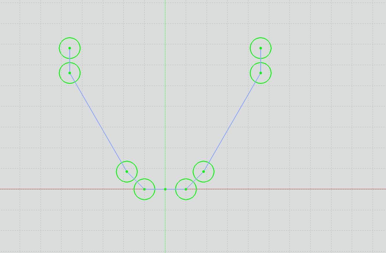
Even better?
The Z-tower Rod distance only 20mm wide, because the passive tower is still ~90mm wide
-
 undefined o_lampe referenced this topic