Euclid facility
-
homeall
G91 ; relative positioning
G1 H2 Z5 F6000 S2 ; lift Z relative to current position
G1 H1 X-355 Y355 F6000 ; move quickly to X or Y endstop and stop there (first pass)
G1 H1 X-355 ; home X axis
G1 H1 Y355 ; home Y axis
G1 X5 Y-5 F6000 ; go back a few mm
G1 H1 X-355 F400 ; move slowly to X axis endstop once more (second pass)
G1 H1 Y355 ; then move slowly to Y axis endstop
G90 ; absolute positioning
G1 X170 Y180 F6000 ; go to first probe point X11.5 Y65.8 Z0 The coordinate put the Z sensor in the center of the bed.
G30 ; Probe; Uncomment the following lines to lift Z after probing
;G91 ; relative positioning
;G1 Z5 F100 ; lift Z relative to current position
;G90 ; absolute positioning -
m401

-
Firstly I would make sure the probe works correctly.
Get the EndStops Monitor plugin from Here
Click the 'Plugins' button on left toolbar
Then click
Select the file you just downloaded, and install it.When it is installed, you need to enable it by clicking the green 'Start' button

Press 'F5' on your keyboard to refresh the printers webpage.
go here
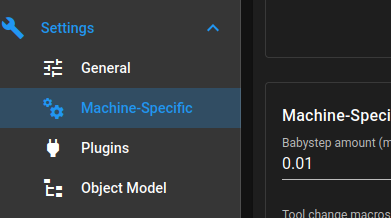
Click the 'Endstops' tab and it will display the status of your endstops

With the Euclid NOT connected it should say 'Yes' under triggered
With the Euclid connected and the switch NOT activated your screen should look like this.
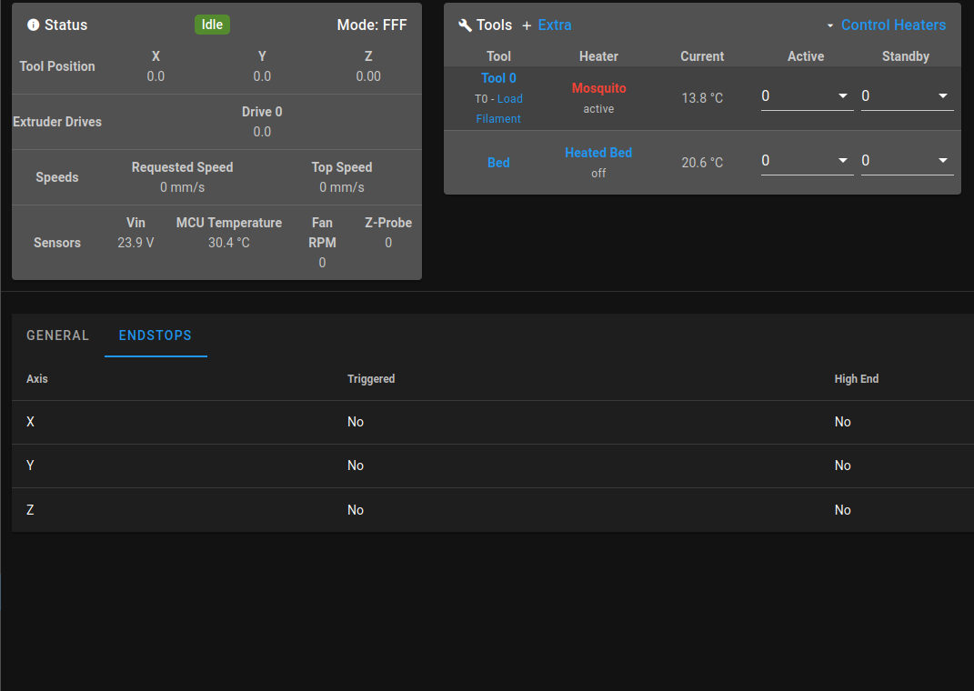
Also note the 'Z-Probe' field in the 'Status' box at the top of the screen
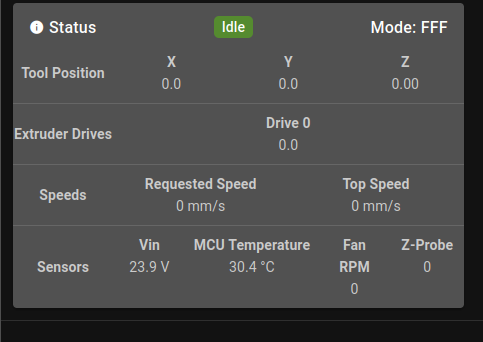
When the Euclid is connected and the switch is NOT depressed it should read 0
When Euclid not connected it should read 1000 and be high lighted in RED
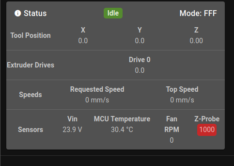
If this is not the case, add a '^' to this line, like mine.
M558 K0 P8 C"^io0.in" H8 F300 60 T9000 A3 S0.01Let us know how you get on.
Regards,
Paul. -
@paulhew
no it did not work when the bed goes up and it coughs the probe sensor the bed does not stop
-

-
-
but i get this error when i do home
10/09/2022 10:07:04 G28
Error: Probe already triggered at start of probing move
Error: Probe already triggered at start of probing move -
@sgk why are you using 2 io's?
Please post your config.g, not just bits of it.
Also a picture like below, WITHOUT the Euclid connected.
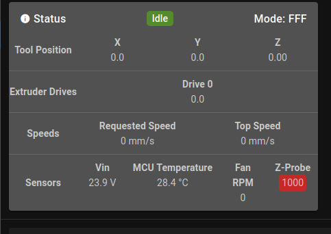
P. -
@paulhew
; ================ Drives mapping =================M569 P1 S0 ; physical drive 0.1 goes forwards - X driver
M569 P2 S0 ; physical drive 0.2 goes forwards - Y driver
M569 P3 S1 ; physical drive 0.3 goes forwards - Z1 Right driver
M569 P4 S0 ; physical drive 0.4 goes forwards - Z2 Left driver
M569 P0 S1 ; physical drive 0.0 goes forwards - extruder driverM584 X1 Y2 Z4:3 E0 ; set drive mapping
; ================ Drives settings ================M350 X16 Y16 Z16 E16 I1 ; configure microstepping with interpolation
M92 X200.00 Y200.00 Z800.00 E693.55 ; set steps per mm - for Matrix extruder:E324.214M566 X500 Y500 Z800 E600 ; Set maximum instantaneous speed changes (Jerk) (mm/min)
M203 X20000 Y20000 Z600 E3600 ; Set maximum speeds (mm/min)M201 X1000 Y1000 Z100 E600 ; Set accelerations (mm/s^2)
M906 X1350 Y1350 Z1200 E700 I10 ; Set motor currents (mA) and motor idle factor in per cent
M84 S60 ; Set idle timeout; ================ Independent Z leveling (original 2 z-axis) =================M671 X-45.0:364.0 Y165.0:165.0 S5.0 ;bed compensation
; ================ Axis Limits ====================M208 X-3.50 Y0 Z0 S1 ; Set axis minima
M208 X330 Y320 Z350 S0 ; Set axis maxima; ================ Endstops =======================M574 X1 S1 P"io0.in" ; configure active-high endstop for low end on X via pin io0.in
M574 Y2 S1 P"io1.in" ; configure active-high endstop for low end on Y via pin io1.in
M574 Z1 S2 ; configure Z-probe endstop for low end on Z; ================ Z-Probe ========================;M558 P8 C"io2.in" A5 H5 F120 T15000 ; set Z probe type to unmodulated and the dive height + speeds (for Mini IR sensor M558 P8 C"io2.in" A2 H5 F120 T15000)
;M558 K0 P5 C"io8.in" H8 F300 60 T9000 A3 S0.01
M558 K0 P5 C"^io2.in" H8 F300 60 T9000 A3 S0.01 ;
;M558 K0 P5 C"^io2.in" H8 F300 T9000 A3 S0.01 ; K0 for probe 0, P5 for NC switch, C for input pin,;G31 P50 X-1 Y-20 Z1.444 ; Set Z probe trigger value, offset and trigger height
G31 K0 P500 X-27.955 Y-18.716 Z1.033 ; CHECK for LOOSE things first! set Z probe triggerM556 S50 X0 Y0 Z0 ; set orthogonal axis compensation parameters
M557 X20:270 Y20:270 P3 ; Define mesh grid
; ================ Heaters ==============================================M308 S0 P"temp0" Y"thermistor" A"Bed" T100000 B3950 ; configure sensor 0 as thermistor on pin temp0
M950 H0 C"out0" T0 ; create bed heater output on out0 and map it to sensor 0 (if NOT using SSR - delete Q10)
M307 H0 R0.312 K0.313:0.000 D13.50 E1.35 S1.00 B0 ; disable bang-bang mode for the bed heater and set PWM limit
M140 H0 ; map heated bed to heater 0
M143 H0 S100 ; set temperature limit for heater 0 to 100CM308 S1 P"temp1" Y"thermistor" A"Hotend" T107537 B4725 C7.06e-8 ; configure sensor 1 as thermistor on pin temp1
M950 H1 C"out2" T1 ; create nozzle heater output on out1 and map it to sensor 1
M307 H1 R2.451 K0.445:0.102 D5.36 E1.35 S1.00 B0 V24.1 ; disable bang-bang mode for heater and set PWM limit
M143 H1 S280 ; set temperature limit for heater 1 to 280C; ================ Fans & Lights ==================M950 F0 C"out7" Q500 ; create fan 0 on pin out7 and set its frequency
M106 P0 S0 H1 T35 ; set fan 0 value. Thermostatic control is turned on
M950 F1 C"out8" Q500 ; create fan 1 on pin out8 and set its frequency
M106 P1 S0 H-1 C"Layers Fan" ; set fan 1 value. Thermostatic control is turned off
M950 F2 C"out9" Q500 ; create fan 2 on pin out9 and set its frequency (lights)
M106 P2 S0.2 H-1 C"Lights" ; set fan 2 value. Thermostatic control is turned off (lights); ================ Tools ==========================M563 P0 D0 H1 F1 ; define tool 0
G10 P0 X0 Y0 Z0 ; set tool 0 axis offsets
G10 P0 R0 S0 ; set initial tool 0 active and standby temperatures to 0C; ===================== Custom settings ====================M572 D0 S0.05 ;pressure advance Set bowden extruder elasticity compensation for E0
M207 S1.5 F3600 Z0.01 ; Set firmware retraction parameters
M564 H0 ; Let the Jog buttons work blv: added to allow jog buttons
; ================ Miscellaneous ==================
;M575 P1 S1 B57600 ; enable support for PanelDue
M911 S10 R11 P"M913 X0 Y0 G91 M83 G1 Z3 E-5 F1000" ; set voltage thresholds and actions to run on power loss
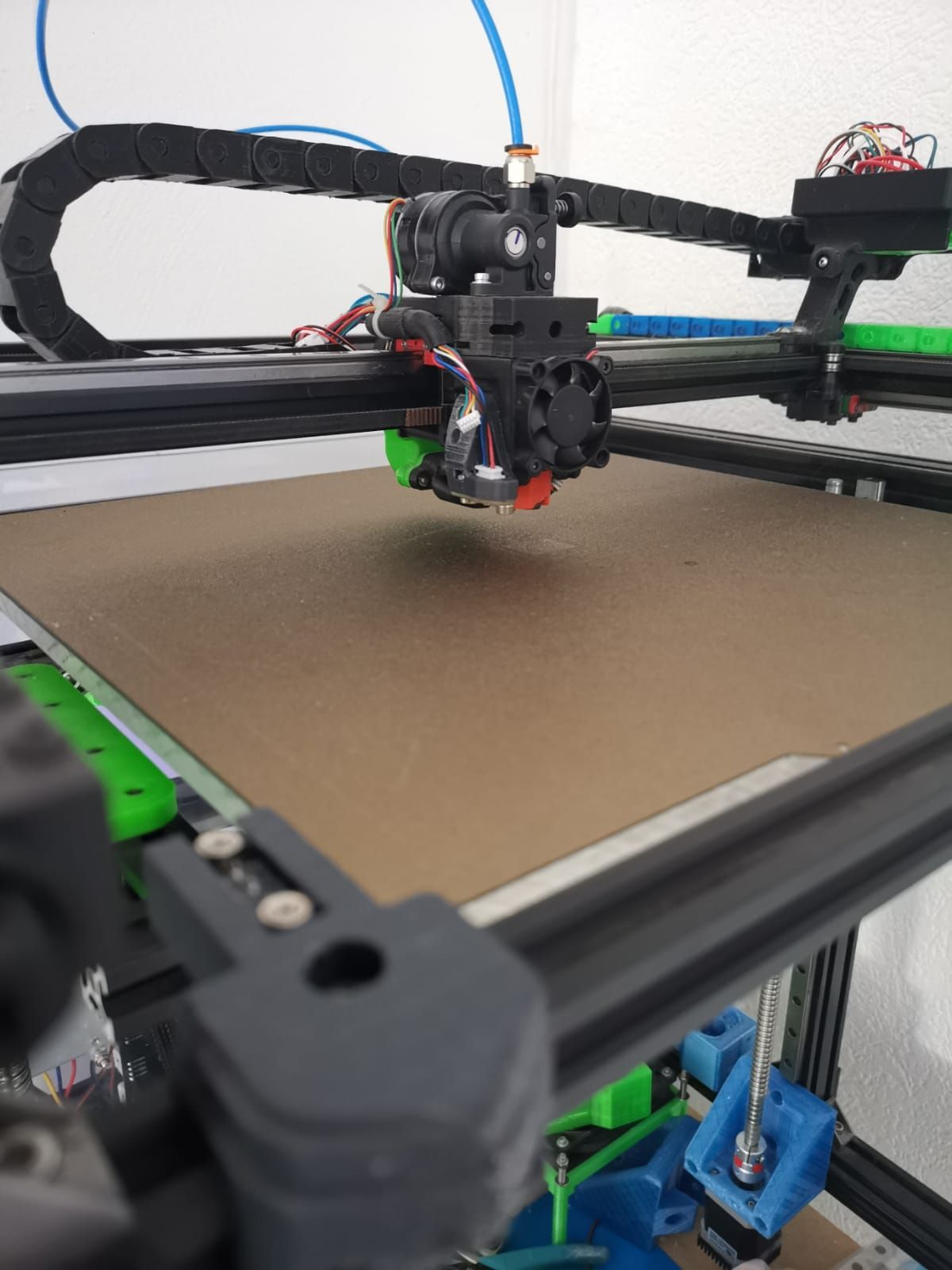
-
when you MANUALLY connect the probe to its dock, does Z-Probe in the dashboard change from a Red 1000 to 0?
-
@paulhew YES
-
now it works but when I launch home I have this error and the probe does not feel the bed I would like to make a video but in this forum I cannot put a video
-
@sgk 10/09/2022 10:50:49 Upload of bed.g successful after 0s
10/09/2022 10:50:07 G28
Error: Probe already triggered at start of probing move
10/09/2022 10:49:44 Upload of bed.g successful after 0s -
example when I do g32 the probe does not feel the bed
-
@sgk said in Euclid facility:
...I would like to make a video but in this forum I cannot put a video
Upload video to YouTube and post the link here.
-
@norder yes ok
-
-
So it homes Z OK.
Just the 4 point mesh is the issue? -
homeall.g deployprobe.g bed4point.g retractprobe.g homez(1).g
These are all my WORKING homing files.
And my config.g
config.gAfter running the Z homing, instead of running G32, type the commands from your homez.g or mine.
G32 iirc runs bed.g, i do not have a bed.g
rename bed.g to oldbed.g
When I run g32, it says bed.g not found, so remove, move or rename it.homez does everything, i think.
You are nearly there.
-
@paulhew Ok thank you very much for your help I will put your files and see what it does.

