Another Power wiring / PSon Question
-
Hi all,
Now that I'm up and running again with much thanks to @jay_s_uk , @Phaedrux, other than my considerations regarding my 8mm cast tool plate, I'm more or less at the stage where I need to start thinking about tidying-up my wiring ready for the tool plate with mains silicone heater.
Can I ask for conformation regarding the power side of things, using a momentary switch to power up the system using PSON.
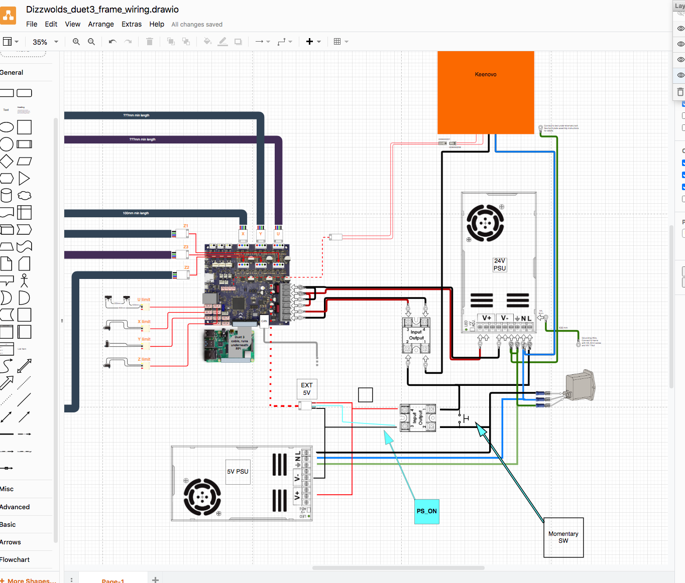
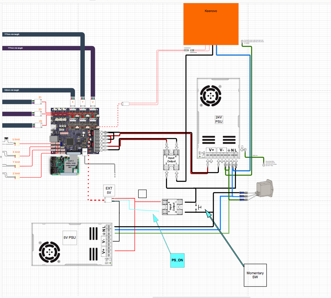
Which of the following diagrams is correct, and or if the rest of my wiring is also correct?Diagram 1,

Diagram 2,

As always, very grateful for your help and advice.
D.
-
This post is deleted! -
I'm not sure what you're trying to achieve.
In both diagrams the Duet board is permanently powered and the momentary switch is just going to provide a pulse of 24V so you could hold that down to power up your heaters (if the duet is calling for heat but not power). I think it very unlikely that's what you're trying to achieve.
If you want the touch switch to be what powers up the Duet, it needs to be on the supply to the 5V PSU, and the SSR switching the PSUs needs to switch both of them.
(Personally I don't like PSUs on SSRs, preferring mechanical relays for PSU switching, but that's mostly superstition.)
You're using OUT0 to drive the bed heater, which is not necesary, but not a problem. You'd have slightly less less wiring to do if you used say 'OUT1'.
You don't seem to have a tool heater connected, nor any fans or temperature sensors (though maybe they are on the CAN).
You've got IO_0 and IO_1 just doing endstops, and they are the two ports that have UARTs on, so I wouldn't put endstops on them - even if you're not using one now, if (say) you decide to add a PanelDue that has to go on IO_0 and then you'd need to rewire. I'd use 2, 3, 6, 8 for limit switches - they are the least capable IO_x. Personally I wire limit switches all 3 connections, but you don't need to.
With respect to the diagrams I really really wouldn't prepare mains wiring diagrams that use (or appear to use) a black line for live (though maybe that's the standard in your jurisdiction).
Finally, with respect to what I think you intend to ask (should you short PS_ON to 0V), no you should not. In your first diagram the PSU-controlling SSR is doing nothing at all - it may as well just be a wire - because your 5V PSU is permanently live, so permanently supplying 5V and 0V to the SSR, so the SSR is always on - so you may as well wire the 24V PSU direct to the mains.
-
@Herve_Smith , @achrn
Thank you for your replies.
I'd never heard of impulse relays before. I'll look further. Thank you.
@achrn said in Another Power wiring / PSon Question:
Finally, with respect to what I think you intend to ask (should you short PS_ON to 0V), no you should not. In your first diagram the PSU-controlling SSR is doing nothing at all - it may as well just be a wire - because your 5V PSU is permanently live, so permanently supplying 5V and 0V to the SSR, so the SSR is always on - so you may as well wire the 24V PSU direct to the mains.
You have some valid points on the power side of things and the use of PSON, which is why I've asked before I do anything.
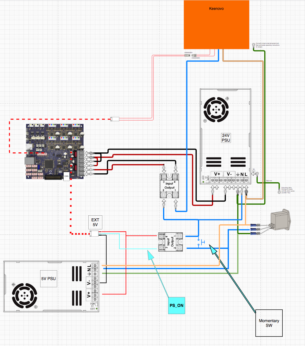
I've made some alterations (not just the colour coding of the wires), to the diagram.
What I'm ultimately trying to achieve is an always On 5v power system, with a momentary switch to fire-up the Duet from the 24v PSU.
The idea of having the 2 x SSR's is taken from gtj0's comments/in the following post as a fail-safe. I don't know what the failure statistics are in comparison of using 2 SSR's compared to a SSR and Mechanical Relay combination;
@gtj0 said in 5v supply using PS_ON to enable 24v and 120v SSR:The other thing you could consider is replacing the relay with another SSR (which is the arrangement I have). That way it would take 2 SSR "permanently closed" failures to energize the bed which would be extraordinarily rare especially if the SSRs were adequately sized and cooled.
I already have 2 x SSR's (TE Connectivity/Tyco SSR-240D50) and 2 x SSRT's (TE Connectivity/Tyco SSRT-240D10), so why not use them is my thought.
Hopefully I have the wiring diagram correct now for what I want to achieve?
Grateful for your input.
-
@Dizzwold said
What I'm ultimately trying to achieve is an always On 5v power system, with a momentary switch to fire-up the Duet from the 24v PSU.
What do you mean by 'fire up' the Duet? The Duet will be running all the time you've got the 5V on. It's the motors and heaters that won't be 'fired up'.
So is your plan that you have a permanently-running process that monitors for 24V and when it sees that it switches on the PS_ON? If your plan for that is daemon.g, you'll need an embedded faster loop (unless you're willing to hold your momentary swicth for at least 10 seconds). I don't think I'd do that.
If you've got the duet running permanently, and you wnat to manually switch your 24V, I think it would be better just to put the momentary switch on one of the IO inputs, set a trigger, and that can switch the power on immediately.
However, I'm not sure why you even want that, because I don't understand why you want the user to be switching the 24V at all. If you scrap the momentary switch, and put
M80in the slicer start gcode, andM81 S1in the slicer end gcode, the Duet will switch on the 24V when it starts each print job, do the print, and then switch the 24V off again when it has finished. No button pressing required. That's what I do (except via a mechanical relay, not an SSR).