CAN Cable for 1LC to Duet 3
-
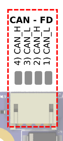
This is probably a dumb question, but I now see that the connector to the 1LC isn’t a full RJ connector. I wasn’t able to find anything on filastruders website about how the pairs are twisted, does anyone know off hand what the best way to convert the cable? I’m assuming I can leave the RJ styled connector for the side that connects to the duet 3.
Is the best way to handle the connection to the tool board to chop the end off and solder on the mini connector?
Thanks in advance!
-
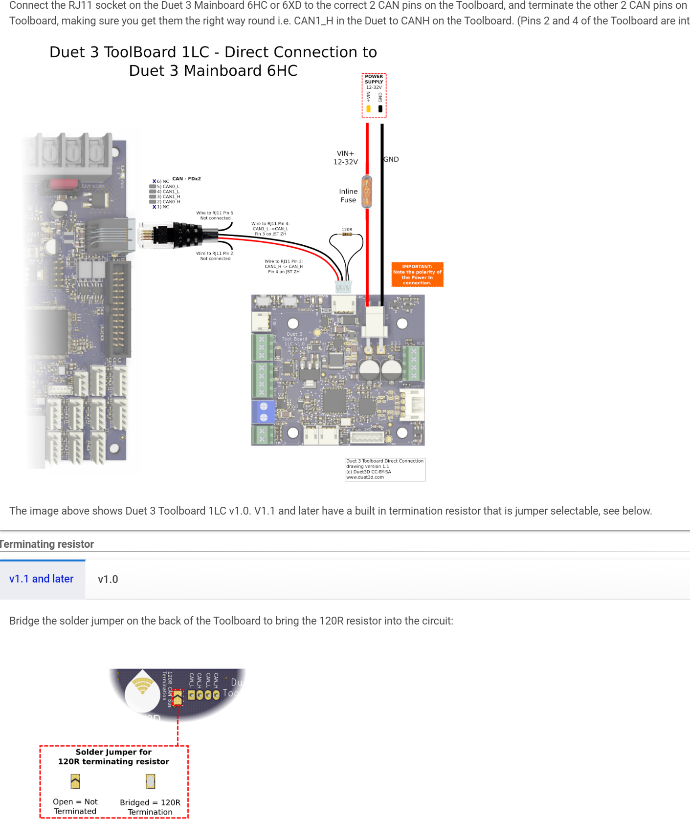
one last clarification, I have a v1.2 board, so soldering the jumper on the back of the board replaces the need for a physical 120ohm resistor for the white and yellow wires (the two right most wires from the JST_ZH connector), correct?
Correct. You can use a resistor as shown if you don't want to wield a soldering iron.
at that point do most people just pull he pins out of the connector or chop the wires very short? I won't be using a tool distribution board for this machine.
Yes, that's fine, just make sure they can't short on anything. Leaving them long, then folding them back over the sheath, and taping over them/shrink wrapping them is also an option.
Ian
-
@michaelr123
That is what it says to do in the 1LC documentation...scroll down to where it says Wiring Noteshttps://docs.duet3d.com/Duet3D_hardware/Duet_3_family/Duet_3_Toolboard_1LC
-
Thanks for the link,
I was hoping for more specifics here as I've never worked with one of these cables and the documentation is a bit sparse. There are more pictures on the old dozuki page, but that's pretty out of date at this point.
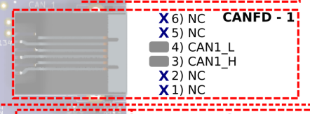
So this is the plug on the Duet 3 board that I'm connecting to and is the CAN1_L and CAN1_H connector. I read something about that only one twisted pair is needed for short runs. Is a short run like less than 100ft or 3ft?
So for my cable from filastruder, yellow H and L (yellow and white & yellow) runs down the center and the green pair is the outside. I'll just solder on accordingly and the green pair goes to nowhere? Does it matter which pair is CAN1 or can either pair be CAN1 to the duet mainboard?


Thanks again, I appreciate you entertaining someone new to the CAN-FD style expansion board.
-
@michaelr123 See https://docs.duet3d.com/User_manual/Machine_configuration/CAN_connection for details of cable requirements and CAN addresses.
See https://docs.duet3d.com/Duet3D_hardware/Duet_3_family/Duet_3_Toolboard_1LC#can section for wiring. If you are not using a Tool Distribution board, click on the 'Connecting WITHOUT Duet 3 Tool Distribution Board' tab for wiring instructions. It's all there.
Ian
-
Thank you much!
one last clarification, I have a v1.2 board, so soldering the jumper on the back of the board replaces the need for a physical 120ohm resistor for the white and yellow wires (the two right most wires from the JST_ZH connector), correct? at that point do most people just pull he pins out of the connector or chop the wires very short? I won't be using a tool distribution board for this machine.

-
one last clarification, I have a v1.2 board, so soldering the jumper on the back of the board replaces the need for a physical 120ohm resistor for the white and yellow wires (the two right most wires from the JST_ZH connector), correct?
Correct. You can use a resistor as shown if you don't want to wield a soldering iron.
at that point do most people just pull he pins out of the connector or chop the wires very short? I won't be using a tool distribution board for this machine.
Yes, that's fine, just make sure they can't short on anything. Leaving them long, then folding them back over the sheath, and taping over them/shrink wrapping them is also an option.
Ian
-
Awesome, thank you very much!
-
 undefined michaelr123 marked this topic as a question
-
 undefined michaelr123 has marked this topic as solved