Deckingman's new printer
-
@T3P3Tony said in Deckingman's new printer:
@deckingman I totally understand your decision but it will be a pity to see that line of exploration come to an end. OTOH you now have a new line of exploration and innovation, like the belts in your new design

Well that original line of exploration doesn't have to come to an end - someone else can always pick up the batten. It's just that I feel I might be getting too old, and lack of funds to do proper investigative work has always been a source of frustration. But I've been open and honest and documented my findings (failures as well as successes) so if anyone wants to pick up where I've left off, feel free.
-
Part 2 is out now if anyone is interested - https://youtu.be/Q4y6v_HUynU
-
@deckingman I prefer to have the crossbeam fixed on one side and floating on the other. Could become relevant for an enclosed and heated chamber.
For the same reason, I'm concerned about the steppers mounted inside of the frame. Unless you want to go watercooled all around...Looking forward to the next video
-
@o_lampe I'm not too concerned about thermal expansion of the X rail - the frame and X rail are made of the same stuff so should both expand at the same rate. I'm not planning on running the chamber much above 50 - 60 C or so, mostly because I'll be using a tool board on the X carriage and the electronics won't be happy much above that sort of temperature. Also it all starts to get too expensive at higher temperatures - not just the components which have to be able to withstand high temperatures, but also running costs. It's still quite a big printer so the volume to heat will be quite significant and with current energy costs here in the UK.......This may preclude my from printing large objects using say Polycarbonate, but that's a compromise I'll have to live with.
The motors are good for 100 deg C continuous operation and having them bolted to aluminium mounts which in turn are bolted to the frame, means that they conduct heat very well and only run about 5 to 10 deg higher than ambient even throwing my existing 2 or 3 Kgs around at 350mm/sec. So if the chamber ran at 60, I wouldn't expect the motors to run much above 70 which should be fine.
The chamber will be more about keeping out drafts and dust as well as being a sound insulator. I'm planning on moving it out of my garage and back into my study which is a spare room next to the one I sleep in - so it needs to be quiet.
For sure, if money wasn't a factor, then I could do things differently but I have to make the best of a very limited budget.
-
This post is deleted! -
@Herve_Smith said in Deckingman's new printer:
I think in light of the obviously vast contribution you have made to the community over the years, that we should consider a "go-fund-me" style campaign to aid in funding an above average standard of rebuild to assist you.
That's a kind thought, but I wouldn't want the pressure. Who decides what "above average" is? I have my own ideas but others may disagree which is entirely their prerogative. I guess what I'm trying to say is that I'll design the printer the way I want it, for my use case, and not to meet some goal that I feel morally obliged to achieve.
I like to think that as a community, we all do our bit to help each other out where we can and further the hobby. So I'll continue to make videos about the design and build as it progresses, and if anyone wants to incorporate any features into their own designs, then I'll haver done my bit. Equally, if anyone feels they would like to make a financial contribution for any tips or knowledge they may have gained from my videos, then a donation via PayPal or Patreon would be very much appreciated and all such funds do go towards the printer and/or making videos about it.
Edit. Links to my PayPal and Patreon accounts are in the video descriptions on my YT channel.
-
@deckingman
I had a bad feeling when you mentioned to sell your mill and lathe after you're done with making parts for the new printer.
My experience is, that I always want to change something after the first testruns, but you'd be stuck with the parts you've got.
At least sell them to the neighbourhood with the option to use them once in a while... -
@o_lampe Yes those thoughts have crossed my mind too. I've had a lifelong policy of never getting rid of tools, which has served me well over the years. But I'm desperately short of space in my single garage and I have nowhere to put a workshop (nor the funds). The other thing is that we have applied to emigrate to Australia to be with our only surviving family (daughter and grand-daughter). Now it might never happen because the only applicable visa for our circumstances is something called a "Contributory Parent Visa" of which only a small number are granted each year. At current projections, it'll be at least 6 years by which time I'll be 76 and one of the criteria is that one must be "in good health" although nobody can say what that actually means. So it might not happen, but if it does, then the lathe and mill would have to go in any case.
-
Part 3 is live now for anyone interested. https://youtu.be/xbRH71qxtik
It covers my design for mounting the print head in such a way that the nozzle can be used for homing Z (something that I've been doing very successfully for a few years). The advantages being that there is no probe to deploy, no offsets, and no hysteresis on the switch part.
I was remiss in not mentioning the fact that the nozzle does have to be heated to soften any blobs of plastic which may have formed (but probing with a hot nozzle is no bad thing as it will negate any thermal expansion effects).
-
@deckingman Interesting way of homing Z!
I have an issue with the way you clamp the hinge part using two wavy washers. The spring forces of these washers will eliminate each other when you put one washer on either side, right? IMHO it would be better to use one wavy washer pushing the LGX mount against a teflon or POM washer.The other thing is the way you mount the V-rollers. I'd use the 4 bolts holding the roller to form a 'box', but you use some extra plates to connect front- and backplate, which seems overengineered to me.
I must admit, I didn't watch the whole videos but scrolled forward to the images, so I might have missed the part where you explained how you deal with the overengineered stuff...maybe use wavy washers between roller and backplate, too?
-
@o_lampe I appreciate your input but unless you watch the video in full, you will reach the wrong conclusions.
There is almost no movement of the "hinge" - well about a fraction of a micron or whatever it takes for the brass screw to break contact with the brass plate. So the two wavy washers will prevent any movement in the X direction, just as the two spring loaded plungers that I use now do. It's a proven design - all I'm doing to eliminate any X movement is to use wavy washers instead of spring loaded plungers. I could use a plain washer one side and a wavy washer the other but that would halve the clamping force but it might be easier to fit. I'll see how it goes when I come to assemble it.
The "extra plates" as you call them have nothing to do with connecting the front and back plates together and is not "over engineering". That would be totally unnecessary. The plates are there solely to proved the slots which keep the belts on the centre line of the X axis, and also to provide a mounting position for the miniature microswitches that make the X axis end stops. They are only 4mm thick and are fixed to both front and back carriage plates so that they do not distort when the belts are tensioned. Instead of a 4mm thick slotted plate, I could have use short thicker plate, half the width of the gantry and fixed to just the front plate, but then belt tension would be applying a twisting force to that plate which is why I elected to fix it to both front and back plates.
-
Part 4 is live now if anyone is interested https://youtu.be/xm0OMHVaiB8
On the theme of this printer being as "all metal" as possible, I've made most of the aluminium parts that I'll need.
-
I'm up to Part 6 now and have made a start on the actual build if anyone is interested https://youtu.be/th-wwZF8akw.
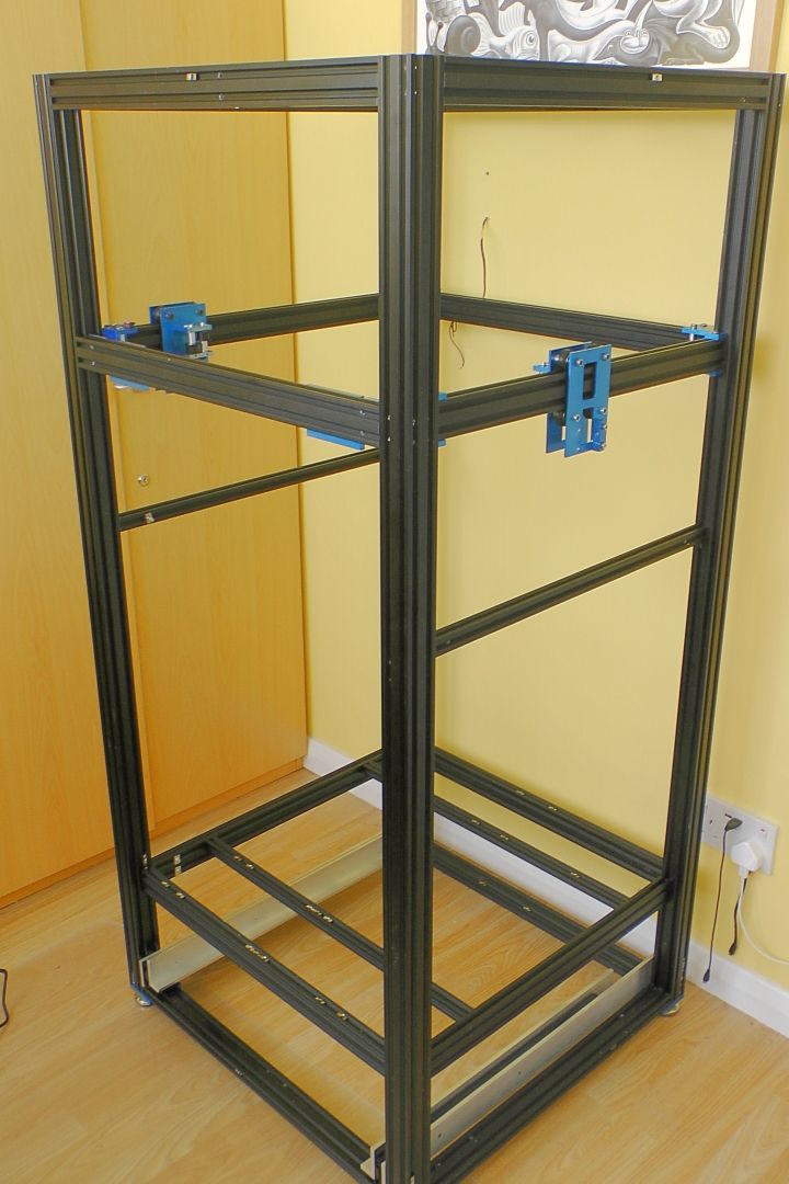
If the video is of no interest, here are some pics
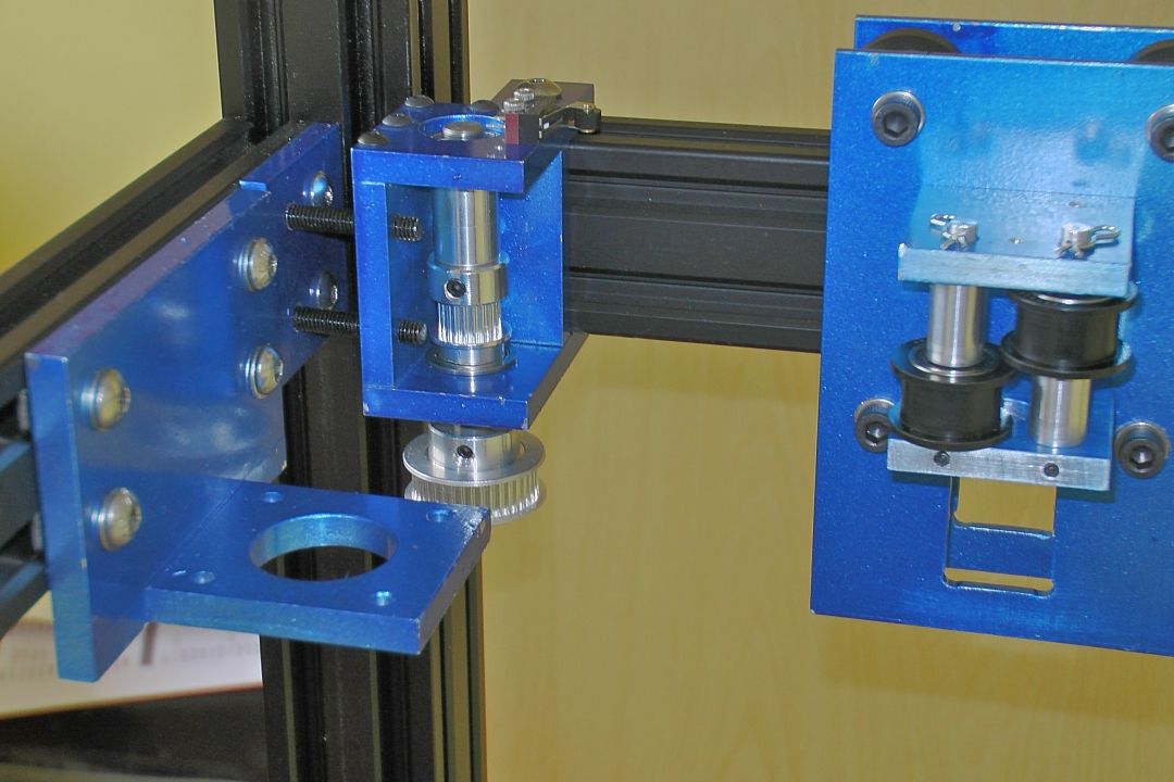
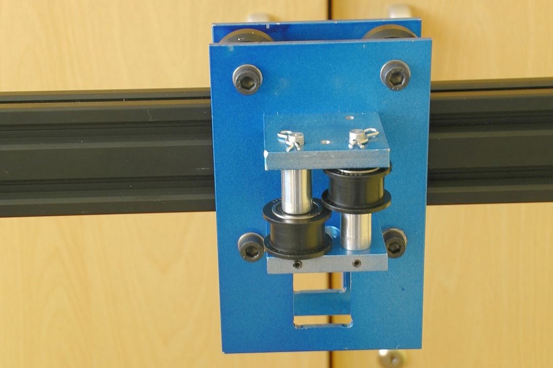
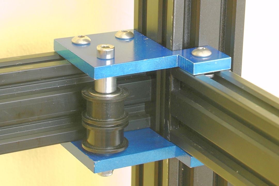
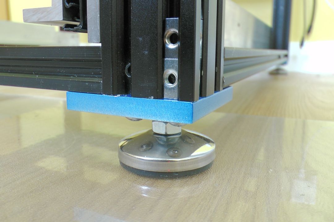
-
Impressive !!!
-
@deckingman Looks quite massive!
Here in germany the openbuild extrusion costs a lot more than standard extrusion. Therefor I'd have only use the v-slot where needed.
But in the UK it might be different, I guess. -
@o_lampe said in Deckingman's new printer:
@deckingman Looks quite massive!
My Wife .......... "I thought you said it was going to be smaller than the old one"
Me ..................."It is. The power supplies will be in a drawer underneath instead of sticking out the back, and there will only be one filament spool which will sit on the top rather than hang off this side".
My Wife ........."That's obviously some meaning of the term "smaller" that I wasn't aware of........".
I didn't tell her that the frame is now 640mm x 620mm rather than 600mm x 600mm.
 The overall height is about 1400mm rather than 1800mm (but I didn't mention that because there could be 2 or 3 Kg roll of filament added to the top).
Here in germany the openbuild extrusion costs a lot more than standard extrusion. Therefor I'd have only use the v-slot where needed.
But in the UK it might be different, I guess.Most of the extrusion came from the old printer so it's all "upcycled". The only extrusion I bought new was four 4040 legs which cost me £118. But I wanted them anodised black to match the rest and cut to length (1350mm). Here in the UK, if you want extrusion cut to length and black anodised, there isn't much difference in price. I bought them from a UK supplier called "Ooznest" which I use a lot and who offer free next working day delivery for orders over £100.
"Tee" nuts, open build wheels, spacers and pulleys were all "upcycled" too as well as all the bolts and fixings, so they haven't cost me anything. I did have to buy some aluminium stock to make the gantry plates, idler mounts, motor mounts, belt tensioners etc. But I've "upcycled" the lead screws and their associated plates as well as the Z motor mount, the Z axis guides and the complete bed assembly (not shown in the pictures). I have plenty of motors as well as a Duet main board and the kind people at Duet donated a tool board. I also have the PSUs and DC UPS but I had to buy some new back up batteries. The big expense was the Bondtech LGX Ace extruder + Slice Engineering Mosquito combo. They did give me a small discount but that was wiped out by having to pay 20% UK VAT when it came into the country plus UPS charged me another £13 for them to take that VAT and pass it on to the government. If I'd bought a Chinese clone, there are no UK import fees which pi**es me off greatly but that's another story....
-
My Wife .......... "I thought you said it was going to be smaller than the old one"
Me ..................."It is. The power supplies will be in a drawer underneath instead of sticking out the back, and there will only be one filament spool which will sit on the top rather than hang off this side".
My Wife ........."That's obviously some meaning of the term "smaller" that I wasn't aware of........".
ROFL .... I can so here this conversation in my mind !!
UPS charged me another £13 for them to take that VAT and pass it on to the government. If I'd bought a Chinese clone, there are no UK import fees which pi**es me off greatly but that's another story....
Count yourself lucky - over here, UPS would be MUCH more brutal.
-
Just uploaded part 7 - https://youtu.be/XLLdK7Bu464
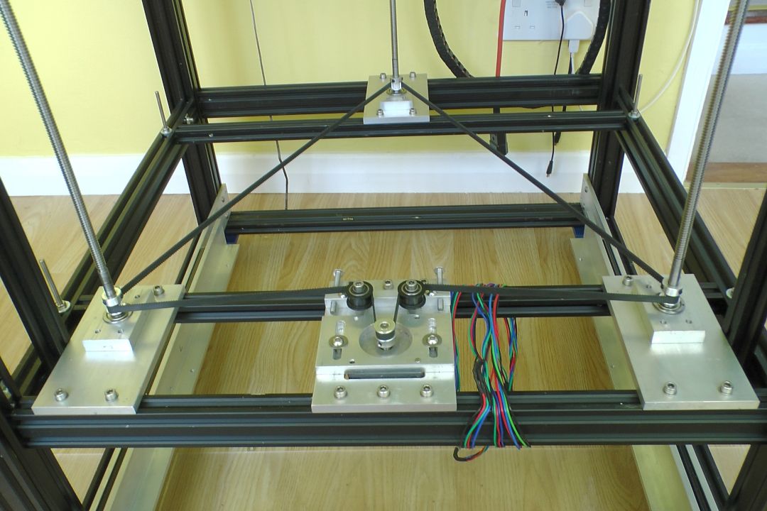
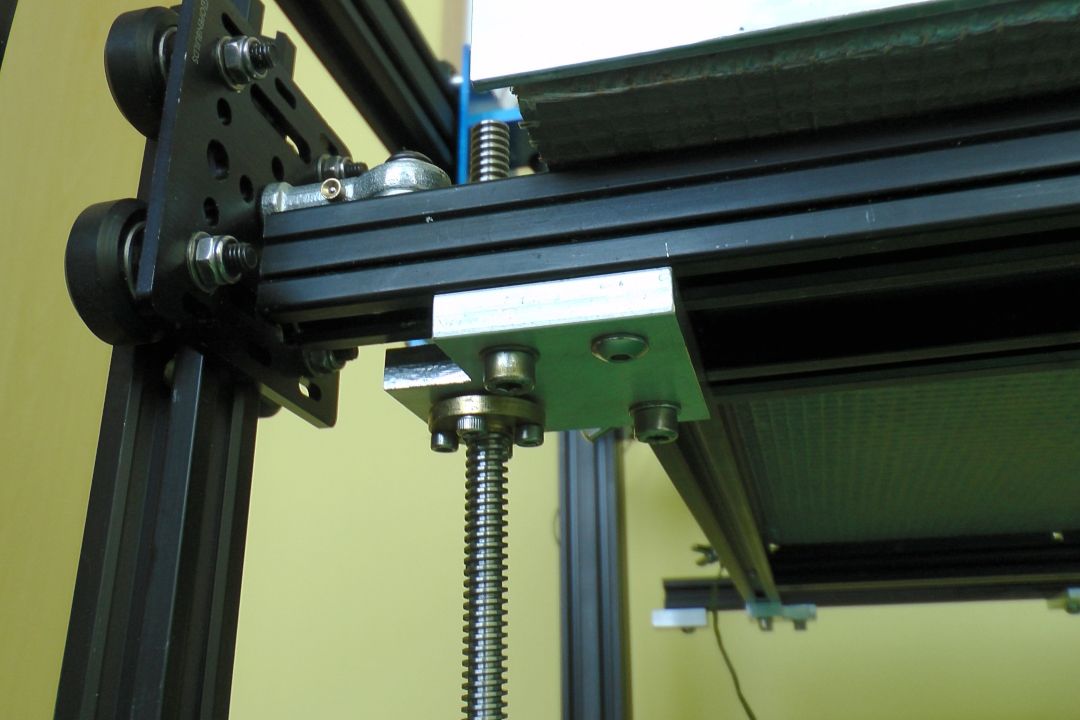
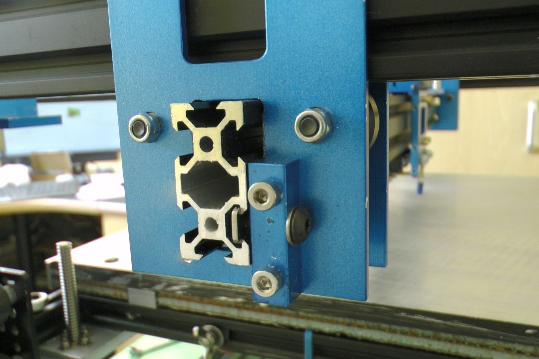
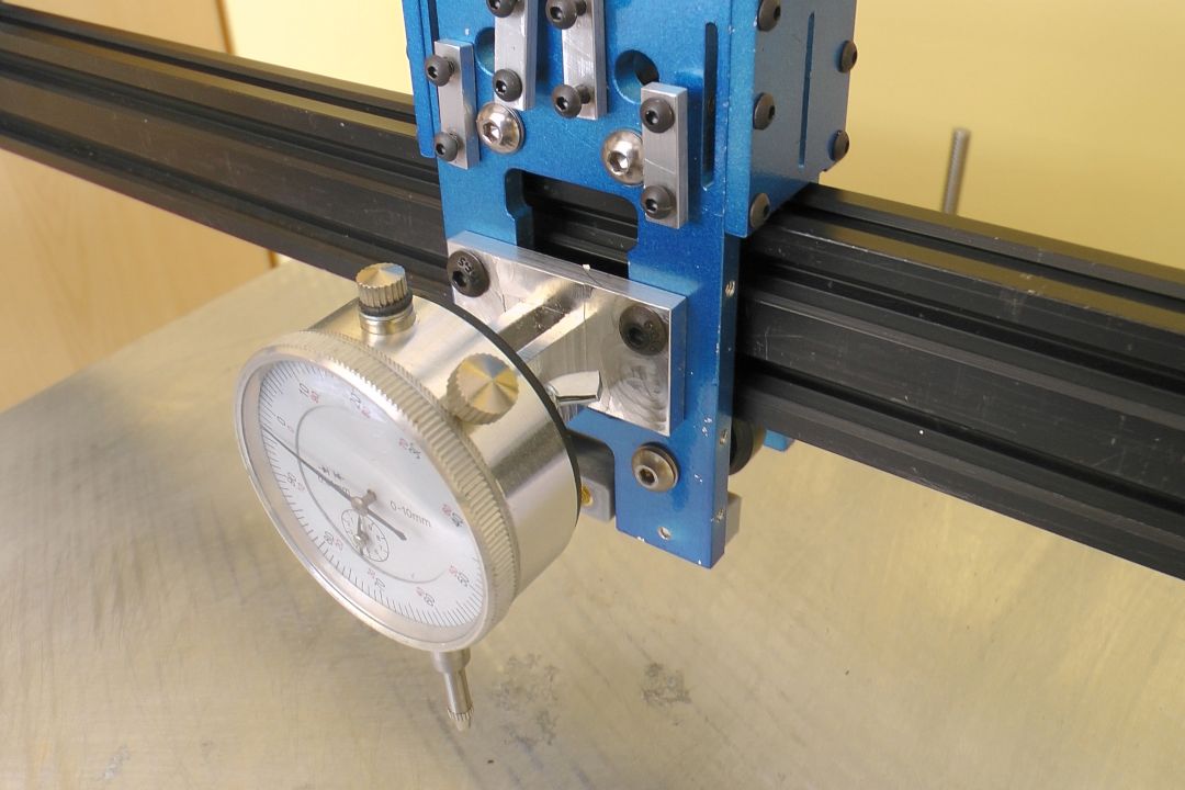
In this video, I explain how a (retired) mechanical engineer gets the build plate level and "tram" such that no compensation of any sort (mesh or otherwise) is needed, nor any further adjustments unless the machine is disassembled.
Here are a few more pics if watching YT videos isn't "your thing".
-
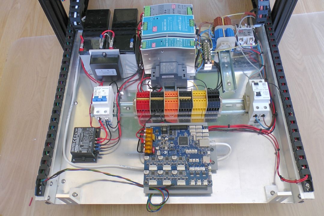
Part 8 is out now. It's mostly just about me installing the various electronics bits and pieces including the DC UPS and batteries in my pull out drawer. https://youtu.be/74u2AluoZgo
Probably boring stuff for members of this forum but there is a bit about keeping the two series connected back-up batteries equalised and protecting them from over-discharging which might be of interest.
Here is a quick picture of the installation so far.
-
This post is deleted!